| John Broskie's Guide to Tube Circuit Analysis & Design |
02 March 2014 New GlassWare Products
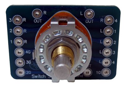
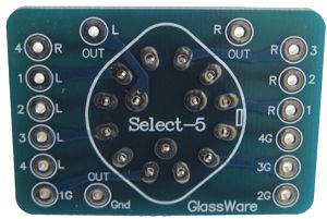
New Select-5 Signal Selector Switch
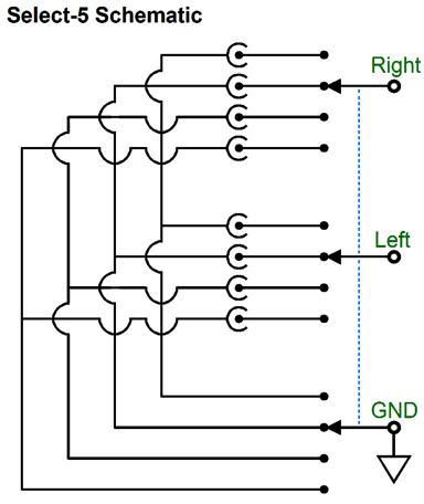
The following schematic looks far more complex than the actual switch circuit is, alas. But you get the idea: three poles and and four positions, allowing four signal sources to be selected independently of each other.
Often, at the line-stage's back panel, two arrays of RCA jacks reside, one row atop the other. The top row consisting of one channel's input signal sources; the bottom row, the other channel's input signal sources. Well, in this setup, we can easily bridge each signal source's two grounds with one wire. Thus, each input signal source would present three connections: Right, Left, and Ground. The Select-5 input signal source selector switch & PCB is available now at the GlassWare-Yahoo store for an incredibly inexpensive price of $18.
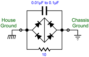
New House-GND Kit For example, say that something goes terribly wrong in your power amplifier and the B+ attaches to the chassis. Well, if the chassis does not make a connection to the house ground, you could receive a lethal shock from touching the energized chassis. But with a solid connection made to the house ground, the B+ voltage would drain away safely. The big problem for us audiophiles is that house ground often becomes contaminated by other electrical devices in your house. This could be avoided, if when they laid out the house wiring, each wall socket got its own separate house-ground wire that in a star-grounding fashion traveled independently back to the houses fuse box and its ground connection. But as this excellent setup would require much more wire, it is seldom performed; instead, most house-ground connections daisy chain their way back to the electrical panel's house ground, much like Christmas-tree lights strung in series. Some electrical equipment is miswired internally, so the neutral and house-ground connections are reversed. This causes something which should never occur: the house-ground wire seeing a sustained current flow. (Ham-radio operators face much more dangerous situations, as lightning can hit the transmitting antenna and then travel through the house wiring until it hits the house ground, setting your house ablaze along the way.) How do you know if you have a dirty house ground connection? Simply attach an AC volt meter to the neutral and house ground connections on the wall socket and read the voltage. It should read 0V. In my listening room, it doesn't, as there is a 500mV AC voltage difference between the two. Is that a problem? Not if you plug a lamp or a toaster into the wall socket, but it is if you plug in some audio equipment, as the resulting hum testifies loudly. The workaround is to use the following circuit.
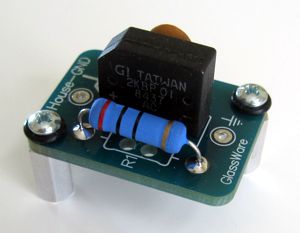
The diode bridge only connects the two grounds when the voltage difference between them exceeds about +/-1.4V. The capacitor allows high-frequency noise to find a path to the house ground. The 10-ohm power resistor makes a DC connection between grounds, while still offering some isolation between grounds.
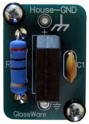
As can be seen from these photos, the new GlassWare House GND kit is quite small, the PCB being only 1 by 1.4 inches big. The House GND kit is available now at the GlassWare-Yahoo store for the stupidly inexpensive price of $9.95. Why so cheap? I needed these kits myself, so made extra PCBs, as knew others need them as well.
Universal Power Booster
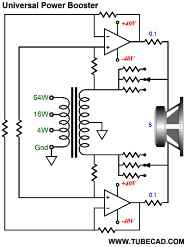
A Universal Power Booster Besides, even four watts is not that much power, no matter how fine sounding, which is a pity. Some loudspeakers require at least 50W to start moving and over 200W to really breathe, for example the Magnapan speakers that I so highly esteem. (Fifty years ago, my stereo system held two power amplifier, a 16W tube amplifier and 200W solid-state amplifier. The first amplifier powered my loudspeakers; the second, the Audio Technica electret headphones that I used at the time. Everyone who saw my setup—naturally enough—assumed the reverse.) Some will argue that revival of horn loudspeakers has led to the revival of small tube amplifiers. But, really, it could be just the reverse: great-sounding small tube power amplifiers created a need for high-efficiency loudspeakers, which horn-loaded speaker achieved easily. Do not forget that a high-efficiency loudspeaker and a big power amplifier are completely compatible, with power in reserve, just as a four-door sedan is more enjoyable to drive about town, if it holds an extra powerful engine, a six or eight cylinder engine versus a four-banger. With power, money, courage, humor, good looks, and wit, reserves are always welcome. Indeed. Sadly, many of us already own fine-sounding small power amplifiers and less-efficient speakers. Not a perfect match, but a better one than the same speakers paired with a big, poor-sounding power amplifier. Still, the optimal setup would be the small amplifier's grace and sweetness augmented by the big power amplifier's extent and muscle. Thus, an ideal power booster would retain the small amplifier's virtues but add the missing power. Here is my idea in a nutshell: the solid-state-based power booster would put out 256W into an 8-ohm load. It could be used with any small amplifier from 4W up to 64W of power. And the small amplifier would actually do some work, adding its power output to the mix. The power booster would run on relatively low rail voltages due to a balanced output. And the power booster could reside in its own chassis, independent of the small power amplifier. This description differs a bit from my previous power booster designs, as they had to be tailor-made to small power amplifier's power output. In contrast, this new design is universal, allowing it to be used with a variety of small power amplifiers. Such an achievement requires that wonderful universal translating device, the output transformer. Loudspeakers used to be sold in three impedances, 4 ohms, 8 ohms, and 16 ohms. Thus, old tube power amplifiers held output transformers with three output taps, 4 ohms, 8 ohms, and 16 ohms. As far as the power tubes were concerned, the load-line they worked into was constant, say 5kohm for example, as the output transformer reflected back to the primary the 5kohm impedance, regardless the speaker impedance (well, as long as it was either 4 ohms, 8 ohms, or 16 ohms). In contrast, solid-state-based power amplifiers usually forgo the benefits of an output transformer, making them cheaper to produce and ship, which certainly are positive features. But these solid-state OTL amplifiers lose a wonderful attribute with the loss of the output transformer: more potential output power and consistent output power into 4-, 8-, and 16-ohm loads. As you can probably tell, I truly like output transformers. Well, in the universal power booster, we get to use an output transformer, but not where you might expect it to be located, at the input, not the output.
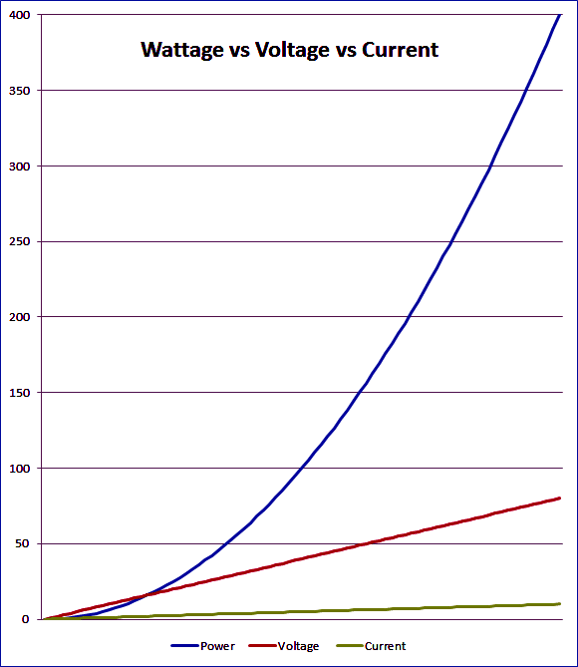
The above output transformer, at the input of the power booster, holds three input taps on its primary, 4W, 16W,and 64W. Of course, more taps could be added, say one for 25W, 36W, and 50W. But for illustration purposes, the three taps are sufficient. By the way, one of the greatest mistakes made in audio history was the rating of power amplifiers in watts. Not that I have anything against James Watt or the measurement of power in joules per second. No, what I do not like is the intrinsic exponential scaling built into wattage. Instead, power amplifiers should have been rated in output voltage (or current) into 8-ohm loads. This would have been a linear scale, which would more closely match what we hear. For example, a 16W amplifier does not sound anything close to twice as powerful as an 8W amplifier. But if the 16W amplifier were labeled as a 16V amplifier we would not expect it to sound twice as powerful as an 11.3V amplifier (more commonly known as an 8W amplifier). And a 64V power amplifier would be expected to sound about four times more powerful as the 16V amplifier, not the 256W divided by 16W, or 16, times more powerful that wattage seems to imply.
Which plot looks more impressive to you? Of course, when loudspeakers came in three impedances, power output made some sense to electrical engineers, and gobs of sense to marketing department types, as 256W is much better advertising fodder than 64V. Okay, returning to the power-booster design, the output transformer can be relabeled in voltage.
If we used percentages instead, it would be labeled 100%, 50%, 25% and 0% for ground. Or, if we used winding ratios instead, it would be labeled 1:2, 1:4, and 1:8. Or, if we used impedance ratios instead, it would be labeled 1:4, 1:16, and 1:64. Nonetheless, the output transformer would have to be fairly big, as it must be able to pass up to 64W to the secondary—roughly the same size as the old Dynaco MK-3 output transformer, the P-431. But unlike the Dynaco MK-3 output transformer, the winding ratios would be much smaller, just 1:2, rather than the P-431's 16.4:1 ratio, i.e. sqrt(4300 ohms / 16 ohms).
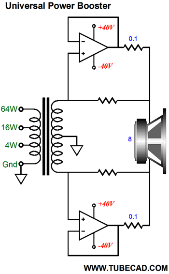
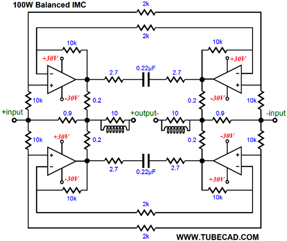
The above schematic is missing many part values, as I do not want to obscure the forest with the trees. The key features are the throwing away of input signal and the development of voltage gain from the power amplifiers within the two impedance multiplier circuits. This was done to allow the use of non-unity-gain-stable power amplifier, such as the LM3886. Here is a more fleshed out schematic, which would require +/-40V power-supply rail voltages and different valued IMC resistors, but you still get the general flavor. Since three primary taps are available on the output transformer, the two IMCs must be setup to deliver three different impedance ratios.
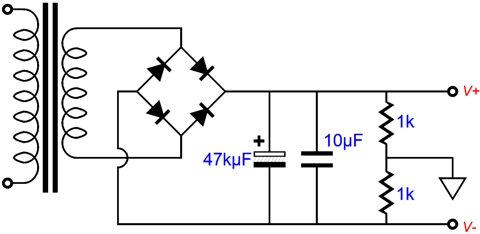
This is a balanced output stage, so the speaker attaches in between the two impedance-multiplier circuits, which allow twice the output voltage swings than what you might expect. For example, with +/-40V power-supply rails, an unbalanced power amplifier could put out +/-32Vpk; and possibly more, with a robust power supply. In contrast, the balanced output stage, with the same +/-40V power-supply rails, could put out +/-64Vpk. And twice the voltage output means four times more power. In this example, 256W versus the 64W for the unbalanced power amplifier. Since the loudspeaker never attaches to ground, the following simple, monopole power supply can be used. A secondary voltage of 56Vac will develop about 80Vdc, after rectification, which is then split into +/-40Vdc by the two-resistor voltage divider made up of the two 1k resistors.
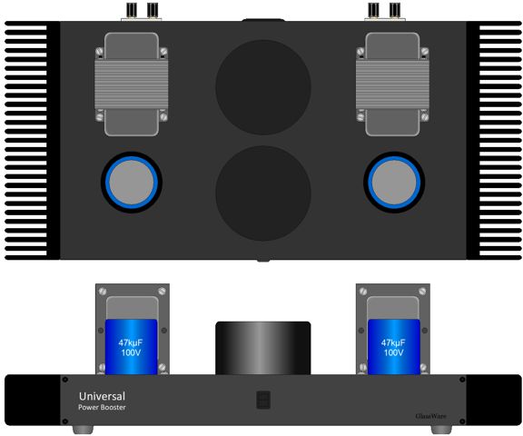
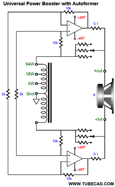
Of course, many smaller 3.3kµF capacitors could be placed in parallel within the chassis, but I would prefer the two big, black capacitors protruding through the top of the chassis. In a way, these capacitors would take the visual place of big output tubes, such as a pair of 6C33 or 845 tubes. By the way, just how much such a project would cost to build is interesting. I mentioned the possible cost of $100 per big capacitor. Now, in general, electronic gear sells for five times the cost of the parts, including the enclosure, which in high-end audio is often the most expensive component. So, if you see a $2,500 power amplifier, could you build the same amplifier for $500. No. Why not? The makers of the $2,500 power amplifier bought the parts in huge quantities, so the $100 capacitor only cost them $80; the $0.10 resistor, $0.01. In short, the maker probably paid half of you would have to pay for all the parts. Thus, if you see a $2,500 power amplifier, you could probably build the same amplifier for $1,000, not $500. Returning to output transformers, we don't have to use an output transformer, as we could an autoformer, as the schematic below shows.
In fact, this might prove preferable, as the autoformer's single winding gives rise to smaller phase anomalies. Note how the autoformer functions something like a phase splitter, providing an inverted signal at its bottom and voltage gain from both its extremes. For example, 8Vpk goes in at the 4W tap and +/-32Vpk develops at both ends, which—with the help of the balanced IMC—creates 256W into the 8-ohm speaker.
Next Time
//JRB |
I know that some readers wish to avoid Patreon, so here is a PayPal button instead. Thanks. John Broskie
Kit User Guide PDFs
And
High-quality, double-sided, extra thick, 2-oz traces, plated-through holes, dual sets of resistor pads and pads for two coupling capacitors. Stereo and mono, octal and 9-pin printed circuit boards available.
Designed by John Broskie & Made in USA Aikido PCBs for as little as $24 http://glass-ware.stores.yahoo.net/
The Tube CAD Journal's first companion program, TCJ Filter Design lets you design a filter or crossover (passive, OpAmp or tube) without having to check out thick textbooks from the library and without having to breakout the scientific calculator. This program's goal is to provide a quick and easy display not only of the frequency response, but also of the resistor and capacitor values for a passive and active filters and crossovers. TCJ Filter Design is easy to use, but not lightweight, holding over 60 different filter topologies and up to four filter alignments: While the program's main concern is active filters, solid-state and tube, it also does passive filters. In fact, it can be used to calculate passive crossovers for use with speakers by entering 8 ohms as the terminating resistance. Click on the image below to see the full screen capture.
Tube crossovers are a major part of this program; both buffered and un-buffered tube based filters along with mono-polar and bipolar power supply topologies are covered. Available on a CD-ROM and a downloadable version (4 Megabytes). |
||


| www.tubecad.com Copyright © 1999-2014 GlassWare All Rights Reserved |