| John Broskie's Guide to Tube Circuit Analysis & Design |
| Post 208 25 July 2011
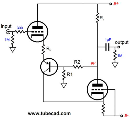
Part three is here and we arrive at where I wanted begin, but knew that I couldn't. In part two, we examined inverting hybrid Op-Amps. Now, we will look into their non-inverting brothers. The following circuit uses a single (PNP) transistor and two triodes.
This hybrid Op-Amp is DC coupled internally, with the coupling capacitor there to protect the following audio device, such as solid-state power amplifier. (Remember that at startup, the tube does not conduct, so the plate will start at the B+ voltage and then slowly fall towards ground potential.) Because of the internal DC coupling, the input tube and output should (must) draw the same amount of current, unlike the inverting examples from Part 2. Why? The output triode sees its input signal at its cathode, not its grid. In order to get the cathode to move up and down its cathode resistor must see a large varying signal current, which will impose a varying signal voltage across the cathode resistor , which the triode will then amplify at its plate in phase. The cathode resistor's value, thus, must be half of what it would be in the inverting version of the hybrid Op-Amp. For example, if 200 ohms were needed in the inverting Op-Amp, then 100 ohms would be needed in the non-inverting version shown above. (We can view this circuit as constituting an elaborate folded cascode that relays the current variation in the input tube to the output tube's plate resistor.) One interesting result is that this Op-Amp draws a constant net current, as the two triodes work in current anti-phase with each other. This is a marvelous asset, as it makes power supply easier, because the input signal's amplification will not bang the power supply about. (Of course, if a low-impedance load is being driven, this Op-Amp will lose its constant-current-draw attribute.) This circuit can really be converted into an unity-gain Op-Amp by removing resistor R1 and shorting out resistor R2. If an even lower output impedance is required, then a cathode follower can be cascaded at the output.
Fancy Hybrid Op-Amp Variations
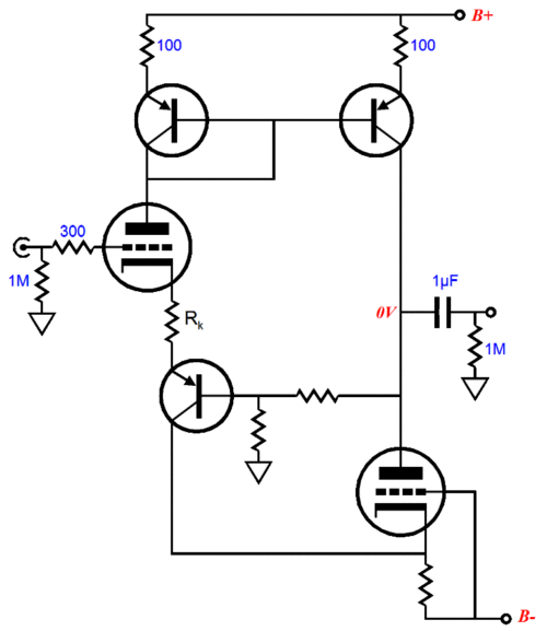
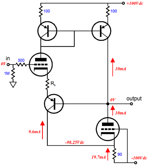
Two high voltage PNP transistors and one additional resistor are all that is needed. As the input tube conducts more current, the current mirror reflects the increase to the output, while the output tube decreases its conduction by equal measure. In other words, the feedback resistor pair and the external load will see the difference in current conduction between the two triodes. So if the input tube decreases its conduction by 1mA, the output tube will increase its by 1mA, with the difference (2mA) flowing through the load. By converting the output stage to a push-pull one, we have effectively doubled the maximum output current swing into the load over the single-ended version. Let's take this in baby steps. Below, we see the circuit at idle, with no input signal. The circuit has been configured as an unity-gain buffer to simplify the illustration of voltage and current relationships. (The two tubes slightly differ in idle current because they see slightly different cathode-to-plate voltages.)
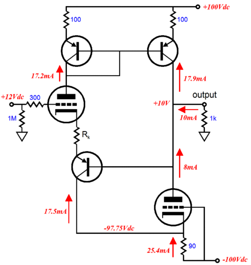
Below, we see a positive-going input signal of 12Vpk, which provokes a 10Vpk output signal. The 1k load draws a peak current of 10mA.
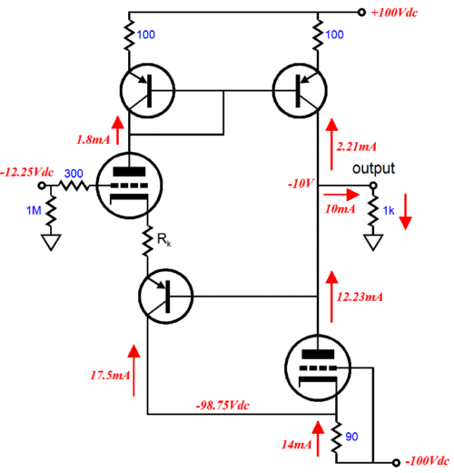
Below, we now see a negative-going input signal of -12.25Vpk, which provokes a -10Vpk output signal. Once again, the 1k load draws a peak current of 10mA. Why is slightly more input signal required when swinging negatively? The triode is not perfectly linear, as it is easier to turn on than to turn off.
If the load impedance had been an easy 47k or 100k, then the non-linearity would have been much, much smaller.
Back to Single-Ended
One problem is that the bottom PNP transistor has only the output triode's cathode-to-grid DC voltage within to operate. And as the transistor's base must be about 0.7Vdc more negative than its emitter, the transistor's effective voltage swing into the triode's cathode will be artificially truncated. One workaround would be to add a few diodes resistor a zener diode to lift the output tube's grid up a couple of volts. (And while we are at it, let's replace the p r with a constant-current source.)
The three diodes impose a voltage drop of about 2.1V. Of course, more diodes could be added or a single zener diode could be used instead. Now just where do we buy a high voltage constant-current source, say one able to withstand 300V? Supertex makes a 450V high voltage linear regulator that could be configured as a high voltage constant-current source, the LR8. Or we could make one out of a high voltage PNP transistor, such as the MJE350.
I don't know about you, but I love the look of this circuit, as it reminds me of a snake biting its tail. On the other hand, I do know that many are wondering where the bypass capacitors across the diode strings are. They can be, maybe must be, added. I left them out of the schematic because I feared making it appear more complicated than it actually is.
Next Time
//JRB |
I know that some readers wish to avoid Patreon, so here is a PayPal button instead. Thanks.
John Broskie
E-mail from GlassWare Customers
High-quality, double-sided, extra thick, 2-oz traces, plated-through holes, dual sets of resistor pads and pads for two coupling capacitors. Stereo and mono, octal and 9-pin printed circuit boards available.  Aikido PCBs for as little as $24 http://glass-ware.stores.yahoo.net/
Support the Tube CAD Journal & get an extremely powerful push-pull tube-amplifier simulator for TCJ Push-Pull Calculator
TCJ PPC Version 2 Improvements Rebuilt simulation engine *User definable
Download or CD ROM For more information, please visit our Web site : To purchase, please visit our Yahoo Store: |
|||


| www.tubecad.com Copyright © 1999-2011 GlassWare All Rights Reserved |