| John Broskie's Guide to Tube Circuit Analysis & Design |
| 30 Nov 2010
|
||||||||||||||||||||||||||||||||||||||||||||||||||||||||||||||||||||||||||||||||||||||||||||||||||||||||||||||||||||||||||||||||||||||||||||||||||||||||||||||||||||||||||||||||||||||||||||||||||||||||||||

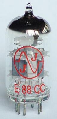
| E88CC R. F. DOUBLE TRIODE | ||
| Base: | NOVAL | |
| Uf = | 6,3 V | |
| If = | 365 mA | |
| Typical characteristic: | ||
| Ua = | 90 V | |
| Ug = | -1,3 V | |
| Ia = | 15 mA | |
| S = | 12,5 mA/V | |
| Ri = | 2,6 kO | |
| µ = | 33 | |
| Limiting values: | ||
| Ua0 = | 550 V | |
| Ua(la=0) = | 400 V | |
| Ua = | 220 V | |
| Ua(War<0,8 W) = | 250 V | |
| PaR = | 1,5 W | |
| Wg1R = | 0,03 W | |
| Ik = | 20 mA | |
| Ug = | -100 V | |
| Rg = | 1 MO | |
| U+k/f- = | 120 V | |
| U-k/f+ = | 60 V | |
| Rk/f = | 20 kO | |
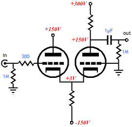
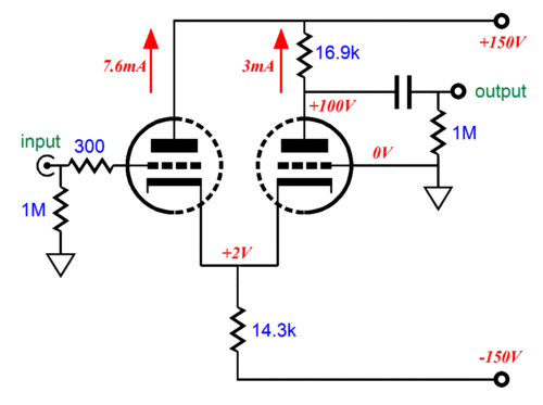
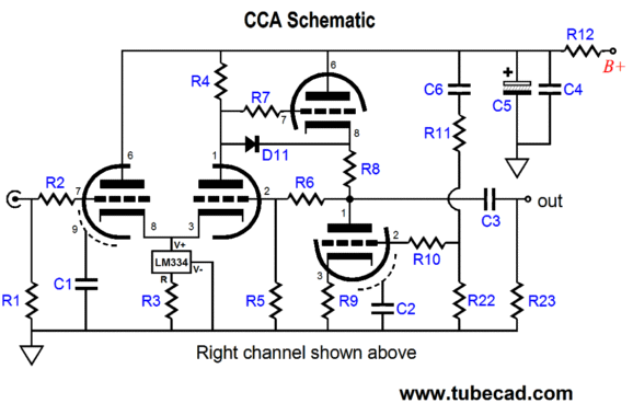
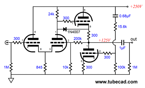
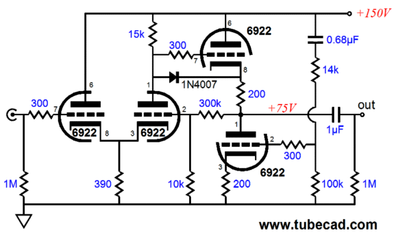
See Blog 62 for more information. So before proceeding, WARNING DO NOT ATTEMPT THIS AT HOME, UNLESS YOU REALLY KNOW WHAT YOU ARE DOING. I tried the 6DJ8 in the CCA, with a B+ voltage of only 150V. (I started with a 120Vac power transformer, which rectified up to about 165Vdc, which was then dropped to 150Vdc through resistors R12 and R17.) Nothing exploded or arced. Furthermore, the sound was surprisingly fine and the gain was close to +20dB. The lower B+ voltage allowed me to use much larger-valued capacitors in the high-voltage power supply (220µF/200V rather than 47µF/450V for C7 & C8 and 270µF/200V rather than 150µF/400V for C5), which greatly reduced the ripple the Aikido cathode follower had to wisk away. In other words, it was dead quiet. I used the following resistor values:
LM334 constant-current source
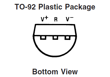
The National Semiconductor LM334 is a well established device. It can be bought in four different packages, but the CCA PCB is configured for the TO-92, three-lead package.
Specifications V+ to V- Forward Voltage LM134/LM234/LM334 40V LM234-3/LM234-6 30V V+ to V- Reverse Voltage 20V R Pin to V- Voltage 5V Set Current (max) 10mA Power Dissipation 400mW ESD Susceptibility 2000V Operating Temperature Range LM134 -55°C to +125°C LM234/LM234-3/LM234-6 -25°C to +100°C LM334 0°C to +70°C Soldering Information TO-92 Package (10 sec.) 260°C
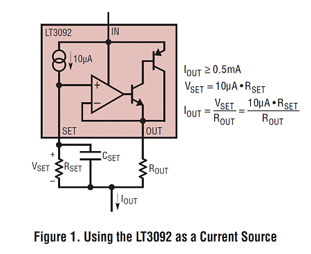
The LM334 requires only one resistor, Rset, to establish its idle current.
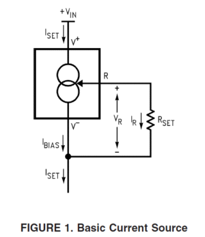
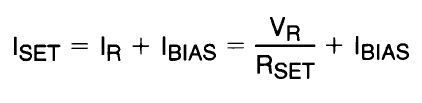
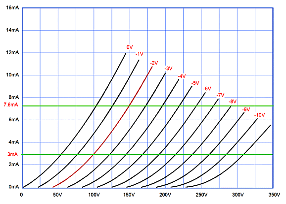
The following graph shows the turn-on voltages and bias currents set by various Rset resistor values.
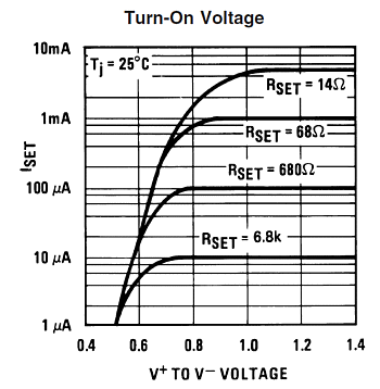
Note that 10mA, the optimal value for most CCA setups, does not receive a resistor value, but we can readily see that 6.8 ohms is the correct value. (The LM334 datasheet goes into much more detail, but for tube work, 6.8 ohms is close enough.) Although 10mA is the LM334's maximum current flow, the device sees less than 10V with most tubes, such as the 6CG7 and 12AU7, so the device's dissipation is usually less than 100mW, well below its 400mW limit. Nonetheless, it is a good idea to attach a small heatsink to the IC, as it better ensures an accurate idle current.
The CCA Power Supplies
The CCA PCB is an All-in-One affair, wherein the audio and power-supply circuitry reside on the one board. The B+ power supply is a simple design that uses cascading pi filters to reduce ripple and rectification nastiness.
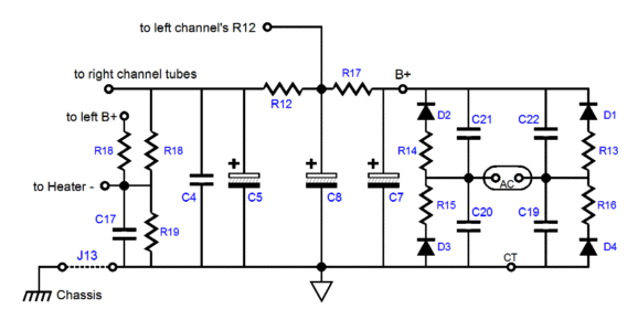
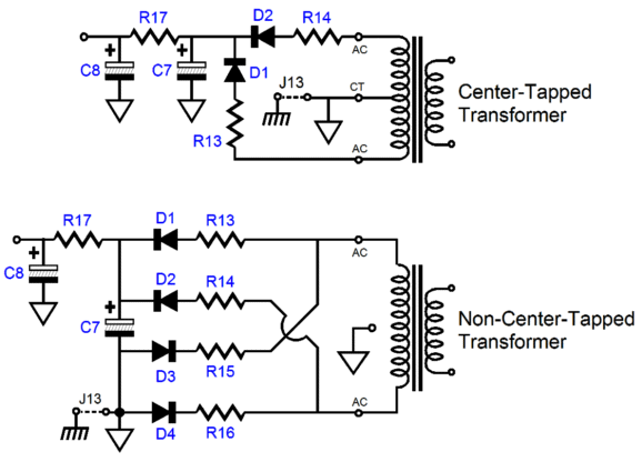
THe CCA PCB can accept either a center-tapped or non-center-tapped high-voltage power transformer. (In my own CCA setup, I used a 240Vac non-center-tapped Hammond power transformer.)
The CCA PCB holds the heater power supply as well and it is regulated.
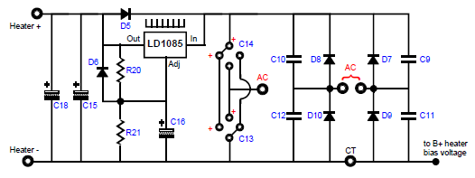
As can be seen, the power supply can accept either full-wave bridge rectifier circuit or a full-wave voltage doubler rectifier configuration. When used as a full-wave bridge rectifier circuit, the two power supply filtering capacitors are placed in parallel by orienting their positive leads to where the heatsink sits; and the secondary attaches to the two encircled AC pads.
Configured as a voltage doubler, these capacitors placed in series by being rotated 90 degrees clockwise, so the positive leads point to the center-tap (CT) pad at the bottom of the PCB; the transformer secondary attaches to both the single AC pad in between capacitors C13 and C14 and AC pad that feeds rectifier D10 and D8; and D7, D9, C9, C11 are left off the PCB. If used as a full-wave center-tap circuit, the two heater capacitors, C13 & C14, are placed in parallel by orienting their positive leads to where the heatsink sits; and the secondary attaches to the two encircled AC pads while the secondary center-tap attaches to the CT pad.
I used a 12Vac/3A transformer, as I like being able to switch the heater power supply on independently from the B+ power supply. By the way, the CCA can easily be built upside down, wherein the tube sockets are soldered to the top of the PCB, but everything else attaches to the PCB's bottom. Why? This allows the tubes to protrude through holes in the top of the chassis. The usual roadblock is the heater voltage regulator, but on the CCA PCB, I placed redundant solder pads on the bottom for the LD1085.
The heater regulator uses the LD1085 low-dropout, adjustable, three-pin, 3A voltage regulator. The regulator can be set to an output voltage between 6V to 25V, but the assumption is that a 12Vdc output voltage will be used for the heaters, so that 6.3V heater tubes (like the 6FQ7 and 6DJ8) or 12.6V tubes (like the 12AU7 or 12BH7) can be used.
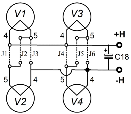
Both voltage types can be used exclusively, or simultaneously; for example a 6GC7 for the input tube and an ECC99 for the output tube. Thus, if the input tubes (V1 and V2) are 6CG7s and the output tubes (V3 and V4) are 12BH7s and the heater regulator output voltage is 12Vdc, then use jumpers J2, J4, and J6.
More RMAF Details
Last time, I mentioned several of the loudspeakers that I liked at the Rocky Mountain Audio Festival, which prompted a friend to ask why I didn't mention any new tube gear. Well, I did see and hear some interesting tube amplifiers. But first let me describe what happened when I first arrived at the show. I walked into a room filled with $200,000 worth of audio gear and I listened to an excellent solid-state power amp through some excellent speakers that cost twice as much as my minivan. How did it sound? Marvelous. So much so that I began to worry about tubes having a harder time competing with so strong a contender.
Imagine a wife or a girlfriend being dragged into a car part store by her significant other. Her expectations of having a good time are low, so she is startled see an impossibly handsome man standing behind the counter. "Maybe I should shop here more often," she says to herself. Upon approaching the counter, she is disappointed to see that the gorgeous face was only printed on a life-sized poster cutout of a famous race car driver and that the actual living fellow behind the counter was only okay looking, with a bad haircut and in need of a shave. Well, this is how I felt, for as pretty as the picture the solid-state amplifier painted was it never felt real. And even when the tube power amplifier rendered a tarnished sonic picture, zits and pockmarks included, the sound still maintained a believability about it. In a nutshell, this is why tubes still matter.
With a Name Like Schiit, You have to Sound Good
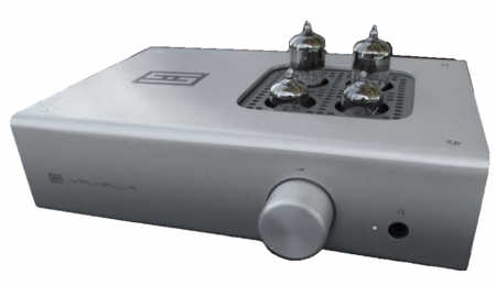
I had great time talking to Jason and Rina at the Schiit table. Jason
Stoddard
is a TCJer and he even used my software in designing his tube headphone amplifier, the Valhalla. Check out the specifications on this cool tube-based headphone amplifier (actually, it is hot to the touch and draws 40W from the wall socket).
I just do not understand how Schiit can make a such an amazing headphone amplifier, an amplifier that is made in America (not China), that uses such high-quality parts (Alps, Nichicon, Wima, Dale, and Neutrik), that uses internal power transformers and not a switcher wallwart, that comes with a 5-year warranty, that sports four tubes and does not use a solid-state output buffer, and that sells for only $349. Amazing stuff.
Schiit also makes a solid-state headphone amplifier, the Asgard (with a name like Asgard...), that sells for only $249. From the Schiit website:
"The Asgard is a fully discrete, Class A, single-ended FET headphone amplifier with no overall feedback and a noninverting circuit topology. Its high-current design makes it uniquely suitable for low-impedance headphones."
If I didn't already own about ten headphone amplifiers, I would certainly buy a Valhalla from Schiit. My only wish is that they paint their boxes flat-black enamel paint. Here's why:
Typical Emissivity of Various Surfaces Material Finish Emissivity Silver Polished Copper - commercial polished Aluminum polished Tin bright Aluminum rough Copper machined Nickel Plate - dull finish Stainless Steel - alloy 316 Steel - rolled sheet Copper - thick oxide coating Steel - oxidized Aluminum - anodized (any color) Paints & Lacquers - gloss finish Paints & Lacquers - flat finish
Taller feet would also prove effective in keeping the little amplifier cooler.

At the Other $$$ Extreme
I saw a lot of interesting audio products at the RMAF and when I asked the selling price, the answer was usually $20k, $30k, $40k, $50K, $60k, $70k... Maybe it was my eyebrows doing somersaults that gave away my astonishment, for the the next thing I heard, over and over, was "Sure it's a lot of money, but don't think that we are making any money off of it." I never knew that such munificence existed in high-end audio. When I think about zero-profit enterprises, $10k record clamps and $70k speakers never come to mind. Or, perhaps, I got it wrong, maybe what I was being told was that they haven't sold any of $70k speakers and they were still searching for their first customer. Nonetheless, it seems to me that if a speaker does not sound better than a Quad 2805 (less than $10k), it should not cost more than a Quad 2805. Either way, there was a lot of super expensive gear on display, even if no one was making any money selling it. Strange, very strange.
So, the only thing I can conclude is that the nice people at Schiit must be making a killing. Of course, ours is a bad economy and I heard from many American firms that if it weren't for the export market, they would be out of business. I also encountered near universal scorn and derision for high-end cable manufacturers. I can understand the logic behind such animus, as it must be painful to see $20 worth of wire selling for more than your power amplifier or loudspeaker or turntable... These cable guys run a markup that would make a jewelry store owner blush. Sure, cables can prove important, but they should never cost more than the rest of your system. Or am I getting this wrong? Would $20 speakers hooked up with $10,000 cables sound much better than $10,000 speakers hooked up with $20 cables?

New Books
The RMAF was not just about audio gear; other items were on display and for sale, such as records, CDs, and books. Finding any new audio-related books is amazing enough, but finding two exceptional new audio books a treasure find. The first is by Robert Cordell and it is titled, Designing Audio Power Amplifiers.
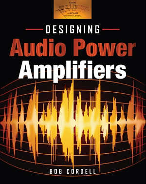
This handsome 600-page book covers aspects of solid-state power amplifier design, from the basics to the secrets only the masters know. The following table of contents gives you a good idea of much material is held between the covers:
Part 1: Audio Power Amplifier Basics
1. Introduction
2. Power Amplifier Basics
3. Power Amplifier Design Evolution
4. Negative Feedback Compensation and Slew Rate
5. Amplifier Classes, Output Stages and Efficiency
6. Summary of Amplifier Design Considerations
Part 2: Advanced Power Amplifier Design
7. Input and VAS Circuits
8. DC Servos
9. Advanced Forms of Feedback Compensation
10. Output Stage Design and Crossover Distortion
11. MOSFET Power Amplifiers
12. Error Correction
13. Other Sources of Distortion
Part 3: Real World Design Considerations
14. Output Stage Thermal Design and Stability
15. Safe Area and Short Circuit Protection
16. Power Supplies and Grounding
17. Clipping Control and Civilized Amplifier Behavior
18. Interfacing the Real World
Part 4: Simulation and Measurement
19. SPICE Simulation
20. SPICE Models and Libraries
21. Audio Instrumentation
22. Distortion and its Measurement
23. Other Amplifier Tests
Part 5: Topics in Amplifier Design
24. The Negative Feedback Controversy
25. Amplifiers without Negative Feedback
26. Balanced and Bridged Amplifiers
27. Integrated Circuit Power Amplifiers and Drivers
Part 6: Class D Audio Amplifiers
28. Class D Audio Amplifiers
29. Class D Design Issues
30. Alternative Class D Modulators
31. Class D Measurement, Performance and Efficiency
As soon as I have finished reading Bob's book, I will give it a proper review; but if you have any interest in solid-state or hybrid power design—or audio design in general, as much of what Mr. Cordell writes about also applies to phono stages and electronic crossovers—then be sure to drop many hints to your loved ones that you would enjoy receiving this book for Christmas. Well written, thoroughly researched, beautifully illustrated, highly recommended.
The second book is not a book, at least not in the typical sense, as it a bookzine. A magazine as thick as a book, but ad free—this is the answer to the question What is Linear Audio? Jan Didden, famous for his many articles in Audio Amateur and audioXpress, is the editor and publisher. He has brought out Volume 0 (yes, zero) and filled it with a who's who of audio design:
Blöhbaum, Frank
Bryner, Andy
Cordell, Bob
Didden, Jan
Gaertner, Jean-Claude
Gerhard, Joachim
Linkwitz, Siegfried
Nousaine, Tom
Pass, Nelson
Polisois, Ari
Self, Douglas
Simon, Ed
Touzelet, Pierre
Wouda, René
Yaniger, Stuart
From the Linear Audio website:
How - Linear Audio is a printed publication, published in a schedule that will be determined by available content of the required quality level. A publication of minimum two issues per year (April and September) of at least 120 pages of technical content is anticipated. I call it a 'bookzine'. Linear Audio will be sold on-line through www.linearaudio.net
By whom - Linear Audio will be published by Linear Audio Publishing from The Netherlands. Content will be selected from submissions from professional and serious amateurs and DIY-ers alike, the sole criterion being the quality and timeliness of the content.
For whom - Linear Audio is meant for anyone who is interested in technical audio developments or who wants to contribute to them. Being employed in audio engineering is not a requirement at all. Happy reading, happy writing, happy building and happy listening!
Loudspeaker, solid-state, and tube design articles abound in this 169 page bookzine. And those 169 pages are ad free. Another way of looking at it that most magazines run about 50% content and 50% ads; thus, Linear Audio would have been 338 pages long had it been filled with ads. In addition, regular magazines engage in funny math to convince their advertisers that they are getting their money's worth, such as printing twice as many magazines as they have subscribers. In other words, the ads pay for magazine's printing. With Linear Audio, the reader pays for it all. Sure that is all very nice, but can't I just read about audio off the net and pay nothing? Indeed, but high-quality articles like these deserve to be printed, which would certainly cost more in paper and toner or ink than the cost of this beautifully put together bookzine.
In short, also highly recommended.
Next Time
I have to come clean, none of what I just wrote was what I had intended to write. I planned on writing about OTL output stages and split-load phase splitters. I will try to catch up soon. In the mean time, be sure to check out the new CCA PCB and kit (only $45 for the PCB and 20-page user guide and only $99 for the PCB and all the parts resistors, capacitors, rectifiers, LDO regulator, LM334 CCS, tube sockets, standoffs and O-rings, except the tubes and coupling capacitors) at the GlassWare Yahoo store. Thanks.
//JRB


E-mail from GlassWare Customers
Hi John,
I received the Aikido PCB today - thank you for the first rate shipping speed.
Wanted to let you know that this is simply the best PCB I have had in my hands, bar none. The quality is fabulous, and your documentation is superb. I know you do this because you love audio, but I think your price of $39 is a bit of a giveaway! I'm sure you could charge double and still have happy customers.
Looking forward to building the Aikido, will send some comments when I'm done!
Thank you, regards
Gary
Mr Broskie,
I bought an Aikido stereo linestage kit from you some days ago, and I received it just this Monday. I have a few things to say about it. Firstly, I'm extremely impressed at the quality of what I've been sent. In fact, this is the highest quality kit I've seen anywhere, of anything. I have no idea how you managed to fit all this stuff in under what I paid for it. Second, your shipping was lightning-quick. Just more satisfaction in the bag, there. I wish everyone did business like you.
Sean H.

9-Pin & Octal PCBs
High-quality, double-sided, extra thick, 2-oz traces, plated-through holes, dual sets of resistor pads and pads for two coupling capacitors. Stereo and mono, octal and 9-pin printed circuit boards available.
Designed by John Broskie & Made in USA
Aikido PCBs for as little as $24
http://glass-ware.stores.yahoo.net/
Support the Tube CAD Journal
&
get an extremely powerful push-pull tube-amplifier simulator for
On Sale only $19
TCJ Push-Pull Calculator
Version 2
Click on images to see enlargements


TCJ PPC Version 2 Improvements
Rebuilt simulation engine
Create reports as PDFs*
More Graphs 2D/3D*
Help system added
Target idle current feature
Redesigned array creation
Transformer primary & secondary
RDC inclusion
Save user-defined transformer
definitions
Enhanced result display
Added array result grid
*User definable
TCJ Push-Pull Calculator has but a single purpose: to evaluate tube-based output stages by simulating eight topologies’ (five OTL and three transformer-coupled) actual performance with a specified tube, power supply and bias voltage, and load impedance. The accuracy of the simulation depends on the accuracy of the tube models used and the tube math model is the same True Curves™ model used in GlassWare's SE Amp CAD and Live Curves programs, which is far more accurate than the usual SPICE tube model.
Download or CD ROM
Windows 95/98/Me/NT/2000/XP
For more information, please visit our Web site :
www.glass-ware.com
To purchase, please visit our Yahoo Store:
http://store.yahoo.com/glass-ware
| www.tubecad.com Copyright © 1999-2010 GlassWare All Rights Reserved |