| John Broskie's Guide to Tube Circuit Analysis & Design |
| 16 Aug 2010 Aikido LSA/HPA is in Rev. A
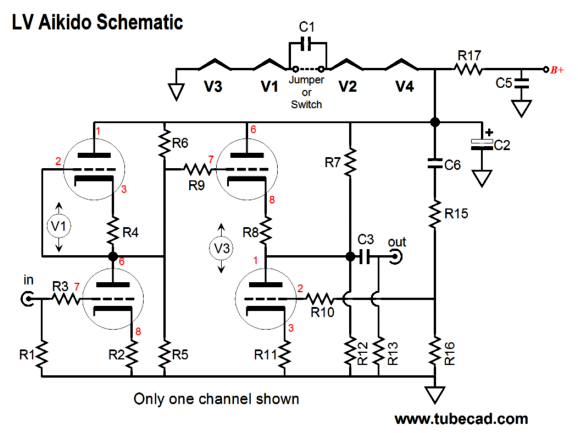
Aikido All-in-One LSA/HPA Rev A What! No absolutely perfect amplifier? Is there an absolute pair of eyeglasses? No, as different eyes require different lenses. Some are thinking, he just doesn't get it; the absolute lies with the object seen, not the observer's eyes. Really; so should all eyeglasses hold perfectly flat plate of glass? Should sunglasses be tintless? Should the welder give up his black safety goggles? In this last case, absolute eyewear would result in absolute blindness. Eyewear serves a purpose. Sometimes the purpose is to enable the wearer to read fine print or to see where the car is going. Sometimes it is to allow us, with night-vision goggles, to see in the dark or, with sunglasses, comfortably to see in the bright sunlight. The "absolute eyewear" is that which absolutely serves its intended purpose. When listening to music, our purpose is primarily enjoyment. The more we enjoy, the closer to absolute perfection our HiFi gear comes. We can never completely arrive, but we should strive nonetheless. Notice that just as there is no absolute eyewear, because there isn't one viewed sight, there is no absolute amplifier, loudspeaker, interconnect... because there is no one musical recorded media. Recordings are like our eyes, some are near perfect, some are grossly flawed. Some sound bright; others, dull. Some sound too distant; others, too close. Some too wide; others too narrow. Some are purely electronically created, with no actual air vibration involved, such as electronic instruments and computer synthesizers plugged directly into the mixing console. Absolute electron anyone? If someone loves a loudspeaker because it reminds him of the sound that he heard in live rock concerts in the 60s, who are we to tell him that he is wrong to esteem so highly such a flawed speaker? What if an aging music lover's ears hear high frequencies with diminished acuity and he prefers speakers with sizzling hot tweeters, should we tell him that his preference is absolutely wrong? An audio Puritan would suffer no hesitation setting these misguided fellows on the right path, lashing them with absolute nonsense, urging them to only buy loudspeakers that are found on a list of approved absolute speakers. Returning to the 9-pin Aikido LSA/HPA, one of the improvements I made was to add the two-coupling-capacitor option to the Rev. A board. I love having the option of choosing between two sonic perspectives with just a twist of a switch.
The old 24V Aikido PCB was a hit. I sold many PCBs and kits and I have gotten great comments from users. (I still listen to headphones with it and it sounds amazingly good as a line-stage amplifier.) The 24V Aikido, however, faced a problem: no 6GM8/6N27P/ECC86 tubes; well, at least no moderately-priced tubes. Not too long ago, the tube was selling for $5, or less; today, they go for closer to $25 to $30; next year, $40 to $50? Moreover, when a supply of a trendy tube grows small, two things happen: obviously, the price goes up and, all too often, the quality goes down. Diminished quality? Here is what happens: a maker of tube gear will snatch up a few hundred 6GM8s; then he will test and separate the tubes in boxes labeled, Faulty (or grossly out of spec), Poor, Good, Fine. He will keep the good and fine tubes and sell the remainder to a reseller (or on eBay). This process of culling and selling back tubes has always gone on, but back in days of tube glory, when all tubes were currently manufactured, it little mattered. A company, such as Marantz or Scott, could use the best 12AX7 or 12AU7 tubes and the rejects would be ultimately sold at a discount to those who didn't care as much, say the owner of a black-and-white TV. But today, with our dwindling supply of NOS tubes, this reselling of rejected tubes quickly muddies the existing pool of tubes; and today very few of those who buy a 6GM8 are going to use in their black-and-white TV. Of course, many of us have a stash of NOS tubes, so such fears do not touch us; as long as I do not live more than 260 years, I'll be set. For others, the ubiquitous 6DJ8/6922/E88CC tube seems a suitable replacement for the 6GM8, but if they ever performed a shootout between the two tubes (under a 24V B+ voltage), they would hear the unambiguous winner, the 6GM8, trounce the 6DJ8; 12DJ8s on the other hand, probably would work just fine under 48V. Thus, over a year ago, when I ran out of 24V Aikido PCBs, I didn't order anymore to be made. Nonetheless, the requests for the PCB keep coming. I fully understand why: high voltage is a pain. I hate being shocked; although it has been over two decades since my last shock, the memory vividly lives on. I hate being nervous when I test a new piece of gear. I like the safety and economical prices of low-voltage power supplies and electronic components. If it were not for the sound bliss that tubes impart… On the other hand, no doubt, there are those whose keen interest in tubes stems precisely from their high price and rarity; no doubt, these audiophiles superciliously dismissed the 6GM8 when it only cost a few dollars, but they now have increased appreciation for the tube's subtle nuances and its new scarcity and high prices only make it all the more desirable. Just imagine how pleased they will be when the little tubes cost $100 each, although the few remaining tubes are likely to be recirculated rejects. (I speak from experience. About ten years ago, I told a friend to buy up a tube for his power amplifiers that was selling for about $11; he didn't, as he much preferred buying $30 competition instead of such a low-rent item—remember, you are only as exalted as your consumption. Last year, I found out that he has been snatching up all of the $11 tubes that I had recommended, but paying closer $75 each. It's just amazing how much better a tube sounds as its price goes up.) The 12SX7 is another triode that works well under paltry B+ voltages. But anyone who knows enough about the tube could easily configure one of my existing octal PCBs, such as the Aikido stereo octal PCB, to use the 12SX7 with a low 48V B+ voltage, placing the heater string in parallel with the ground and B+ voltage. In addition, the 12SX7 is becoming ever more expensive and is suffering from reject recirculation. After experimenting with several current-production tubes, I discovered that the 12BH7 and JJ ECCC99 worked surprisingly well in an Aikido line-stage amplifier with a B+ of only 48Vdc. I planned on making a new PCB production run on the 24V Aikido PCB, but I realized a problem. The 24V Aikido board also held a solid-state unity-gain power buffer for driving headphones. By doubling the B+ voltage from 24Vdc to 48Vdc, the buffer's dissipation would also double. I knew some users were already at the end of the heatsink's limits and different and more expensive solid-state devices would be needed. So I set out laying out a much larger PCB, large enough to hold bigger heatasinks and a power supply rectification circuit and regulated power supply. The board was getting big, much bigger, too big. I halted this design effort and decided to go in the other direction: smaller. I jettisoned the solid-state buffer and the idea of incorporating a full power supply on the board. The result was an astonishingly small PCB, only 3.6in by 5.4in big.
As you can see, the PCB, selector switch, on-off switch, and stepped attenuator easily fit inside a Hammond extruded enclosure. If the selector switch and attenuator are not needed, for use with a Squeezebox unit for example, the board can be fitted into a much smaller extruded enclosure. The LV Aikido PCB and kit are available now at the the GlassWare/Yahoo store. I only have eight 12BH7s and twelve ECC99s in stock, so they will sell out quickly.
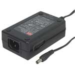
LV Aikido Power Supply The genius of the Aikido circuit is found in both its low distortion/low output impedance, and great PSRR figure. Nonetheless, a good power supply helps (there is a practical limit to how large a power-supply noise signal can be nulled). I recommend you use at least a robust, fast-diode rectified power supply. A regulated power supply is the obvious upgrade. The LM317HV can be used with B+ voltages up to 48Vdc, as long as the raw DC power supply voltage feeding the regulator is not over 57Vdc. The power supply is external to the LV Aikido PCB and can be mounted in, or outside, the chassis that houses the PCB. The optimal power supply voltage depends on the tubes used. Four 6GM8s (6N27P/ECC86) can be used with a low 24V power supply, with 12BH7 or ECC99, 48Vdc—either a switch-mode or a linear power supply. After dealing with 400-volt power supplies, it is a joyful relief to work with relatively low voltages. We must address, however, a few important issues. For example, although we do not need much voltage, the heaters add a heavy current burden on the power supply. With 6GM8, the heater string requires 330mA and the four tubes require a total of 8mA, for a grand total of 338mA or (rounding up) 350mA. So, 0.35A against 24V equals 8.4W of dissipation. With the ECC99, the heater string requires 400mA and the four tubes require a total of about 10mA, for a grand total of 410mA or (rounding up) 450mA. So, 0.45A against 48V equals 21.6W of dissipation. (In other words, expect a good deal of heat and provide plenty of ventilation, in spite of the low B+ voltage.) The LV Aikido is a perfect candidate for a wall-wart power supply. Both linear and switch-mode wall-warts are available with a 24V output voltage and both cost less than $30 USD. A medical-grade switch-mode power supply cost about $45 and it will be both safer and more quiet. On the other hand, a simple non-regulated power supply can be built from a power transformer, diode bridge, and a few capacitors and, maybe, a choke. For my own LV Aikido, I bought a Mean Well 48Vdc/800mA switcher power supply from Jameco for only $24.95.
The key feature is the small 150mVpk-pk of ripple, as some switcher power supplies put out closer to 1Vpk-pk of ripple. I would prefer 1mV of noise. Fortunately, the ripple frequency is supersonic, say 40kHz to 80kHz, which allows us to use a simple RC filter to scrub the ripple from the DC voltage. The LV Aikido PCB holds pads for such an RC filter. I used a 1-ohm resistor (R17) and a 1kµF 63V capacitor (C2) to post filter the incoming DC. Alternatively, an LC filter could be put in place by substituting the resistor (R17) for a small, low-DCR hash choke.
If the idea of a switching power supply is too creepy for you, or if you do not like external power supplies in general, then a preassembled linear regulator that holds its own power transformer might be the best choice. Mouser sells a IHB48-0.5 linear regulator made by International Power for $45 that puts out 48Vdc @ 500mA.
This type of preassembled linear regulator is used all the time in industrial equipment. They are wonderfully self-contained and robust. Their downside is that they are often physically large and, occasionally, they buzz. I once owned a linear regulator made by one of International Power's competitors that suffered from a transformer stack that had become unglued and rattled terribly, making it far too noisy ever to use in an audio project. I sent it back to the maker to have it fixed and, a few months later, they sent right back to me, saying that although it was crazy noisy, it was well within their tolerance specifications. It ended up in the garbage. An additional shortcoming with this type of power supply is that they use only the most pedestrian of electronic parts; hence their rubustness and occasional buzzing. Moreover, the parts are often hot-glued or silicon-sealed to the PCB, making their removal difficult. Still, such a power supply could work beautifully, as its 10mV of ripple and noise is wonderfully quiet compared to the switcher power supply, although the ripple frequency will be at 100Hz or 120Hz, not some supersonic frequency. I have been describing 48V power supplies exclusively, but the LV Aikido can also be used with 6GM8/6N27P/ECC86 tubes and a 24V power supply. The lower B+ voltage grants us many more options, as 24V regulated power supplies, both switching and linear, are readily available.
LV Aikido Power Switch
Why No Headphone Buffer? My hope is to design a fine standalone, solid-state, unity-gain power buffer that can be used with the LV Aikido board. This explains all the Triadtron circuits with which I have abused the pure-tube-of-heart readers recently. I want something special. Not the generic diamond topology, although such a buffer made from discrete components can sound surprisingly good, but just not good enough. One outlandish idea I have is to design a buffer so robust that it could drive 8-ohm loudspeakers. Given a 24V power supply, such a buffer could readily swing 8Vpk into an 8-ohm load, which would equal 4W of average power (RMS). I have heard several 2.5W amplifiers and I know that with high-efficiency loudspeakers, 2.5W can play thunderously loud. With a 48V power supply, such a buffer could readily swing 20Vpk into an 8-ohm load, which would equal 25W of output. If you are single-ended amplifier lover, 25W will sound huge. But if you run monstrously big solid-state power amplifiers that, during crescendos, cause the lights to dim throughout your neighborhood, you probably do not read the Tube CAD Journal, so it little matters what you think about 25W ;) Imagine a 17in wide chassis with an LV Aikido at its center and with two big heatsinks and a stiff power supply. I would love to hear such a beast.
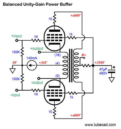
Balanced Power Buffers
Above, we see two matched power pentodes, such as the EL34, 6550/KT88, KT99, KT100, run in pentode mode with a constant-current source setting the idle current and limiting the power buffer to strict class-A operation. With a constant-current source set to 140mA, about 20W could be possible. The output tubes' cathodes attach to the output transformer's secondary and the secondary's center-tap attaches to the constant-current source. This configuration establishes a direct feedback path into the tube, so the output impedance and distortion will be respectably low, in spite of the pentode operation. Note how the 4-ohm tap is used to connect to the constant-current source and the 16-ohm and ground taps are used to connect to the cathodes and loudspeaker. If the output transformer does not hold a center-tap, it cannot be used. Wait a minute, isn't the 8-ohm tap midway between the 16-ohm and the ground tap? No. Reflected impedances do not divide that way. To deliver equal wattage into both 4-ohm and 16-ohm loads requires that the 4-ohm load see half the voltage that the 16-ohm load sees. The unlabeled resistor that connects the B+ to the screens should have its value be experimentally found. By the way, if a regulated power supply is used, the two screens can share the same resistor without the 47µF capacitor; but with the typical noisy, high voltage power supply, the capacitor is essential. (By the way, a clever trick is to feed the screens a regulated voltage, leaving the plates' B+ voltage unregulated, but still achieving most the benefits of a fully regulated power supply on the cheap.) Also note how the buffer's outputs are floating at the cathode voltage, which might prove dangerous. The workaround might be to use many EL84 output tubes instead, as their cathode would be only about 15Vdc. Another workaround is to place the ground connection at the secondary center-tap, making the outputs ground referenced.
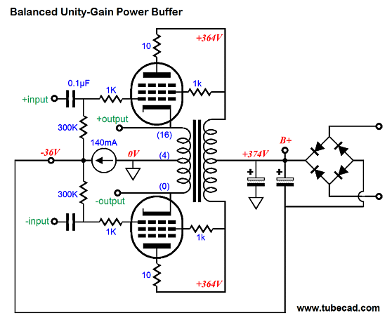
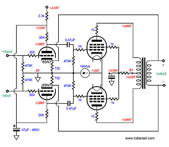
In the above schematic, a few changes have been made: the ground attaches to the secondary center-tap, two coupling capacitors have been added, and the output stage is now configured in triode-connected mode. The same 410Vdc power supply is used. Surely, you mean 400Vdc power supply? No, 410Vdc; do not forget the voltage drop across the primary's DC resistance, as most solder slingers do. Why the switch to triode mode? By shifting the ground connection to the other side of the constant-current source, we have dramatically improved the PSRR of the buffer, as almost all of the ripple resides on the -36V terminal, the constant-current source isolating the buffer from the ripple. Since we now have a clean B+ voltage to work with, we can switch back to triodes. (Or we could stick to pentode mode, removing the RC filter at the screens, directly attaching the screens to the B+ connection.) The danger with such a setup is that many will attach the ground to both sides of the constant-current source, so strong is the habit of grounding the power supply reservoir capacitors. The two coupling capacitors may appear as a huge liability, which makes sense, as placing more in the signal path means more can go wrong. But in this case, I believe the risk is worthwhile, as I want to limit the low-frequency response of the buffer, welcoming the added high-pass filter for my satellite loudspeakers. By the way, if much care is taken, and if the signal source already holds two coupling capacitors at its output, and if signal source and power buffer do not make a common connection to the house ground, the coupling capacitors could be left off, using the signal source's capacitors in their stead. By the way, if the distortion or output impedance proves too high, or if the secondary does not hold a center-tap, or if the input signal requirement is too great, then the following circuit might be a solution.
It may look like a power amplifier, but this circuit is still a unity-gain power buffer. The 6SN7 input tube that receives the balanced input signal is in charge of the output tubes. The secondary is DC referenced to the 6SN7's cathode voltage and if effectively shunted by a 1464-ohm resistance (the two 732-ohm resistors in series). Large balanced input signal swings are still needed, as the secondary will swing the cathodes up and down with the in-phase output voltage swings. The internal coupling capacitors can no longer be used as a free high-pass filter, as they reside within the feedback loop. In fact, because we are now including so much more within the feedback loop, much greater care must be taken in transformer selection and layout. Nonetheless, this power buffer might be the absolute best solution for some. For example, imagine taking the balanced output voltage signal from a DAC that holds a 2.5V DC offset. This offset becomes an asset, when driving a tube-base differential amplifier, whose cathodes are tied together and share a common Constant-current source, as the 2.5V gives us more voltage within which to establish our constant-current source. Thus, a 12AX7 's 1.5V to 2V cathode voltage would be added to the 2.5V DC-offset voltage, giving the constant-current source 4V to 4.5V voltage window within to operate, alowing us to use an IC constant-current source, such as the LM134. And since the constant-current source finds no negative power supply connection, these few extra volts are welcome. In addition, the 12AX7's high gain could easily drive any of these power buffers to full output. Such a setup would be truly minimalist and could sound marvelous.
Next Time
//JRB |
E-mail from GlassWare Customers
High-quality, double-sided, extra thick, 2-oz traces, plated-through holes, dual sets of resistor pads and pads for two coupling capacitors. Stereo and mono, octal and 9-pin printed circuit boards available.  Aikido PCBs for as little as $24 http://glass-ware.stores.yahoo.net/
Support the Tube CAD Journal & get an extremely powerful push-pull tube-amplifier simulator for TCJ Push-Pull Calculator
TCJ PPC Version 2 Improvements Rebuilt simulation engine *User definable
Download or CD ROM For more information, please visit our Web site : To purchase, please visit our Yahoo Store: |
|||||||||||||||||||||||||||||||||||||||||||||||||||||||||||||||||||||||||||||||||||||||||||||


| www.tubecad.com Copyright © 1999-2010 GlassWare All Rights Reserved |