|
10 February 2010
It's About Time
Yes, it’s been an unpardonably long time since my last post. I have been crazy busy with life and, rather paradoxically, new PCBs. I have to test each new PCB design and create all the needed documentation, such as part labels and user guides and photographs—all of which takes more time than I could ever imagine. So, special thanks go out to Tom in Rancho Cordova, who is helping test one new PCB, and to my good friend, Glenn, in Sacramento, who helped me with the instructions for the tube clock shown above.
Tube clock? Is it a piece of artwork, worthy of window display in exclusive art galleries? Or is it the long-awaited analog replacement to the famed Tice digital clock? Or is it a chronometer of exceptional precision? Or is a timepiece of uncanny beauty, suitable for adorning walls of Beverly Hills mansions and Manhattan penthouses? Or is it something like a badge of affiliation to an almost cult-like adoration of vacuum tubes? Well, it’s all of the above. It is also my latest kit offering.
The tube clock’s dial face is an 8-inch diameter circle made from the same extra- thick 0.93-inch, FR-4, double-sided, 2-Oz copper PCB material from which all my PCBs are made (the tube symbols and hour marking dots are actually large solder pads and are bright and shiny, so almost impossible to photograph). The clock movement, like the clock face, is made in the USA and is accurate to 1 second per day; it runs on one AA battery, which should last about one year. The clock hands are two colored: black on one side and white on the other, as shown above.
The clock's design is based on original artwork by my cousin, John A. Broski. I know that many are asking, Why a kit and not a completely assembled clock? Quite simply, I do not trust the post offices of the world; the French post office has managed to deliver one PCB folded in half and other post offices have crushed packages, breaking tubes and leaving large holes that parts pour through. Admittedly, such catastrophes are extremely rare and I have had even UPS deliver assembled and glass-besseled clocks to me in great shape, but I would feel much better knowing that the clock movement and hands were absolutely safe.
Besides, anyone who can replace a phono cartridge should easily be able to assemble the tube clock in less than a minute, as the clock movement comes completely assembled and only requires its insertion into the clock face and the attaching the clock hands (with one nut). Of course, there are those who cannot readily replace a cartridge or fix a broken TV or rebuild a transmission—and how I envy them. Because I can, I am always doing what others would leave for the professional appliance repairmen and auto mechanics. (I know a fellow in Silicon Valley who charges $500 to replace coupling capacitors in the high-end tube gear owned by lawyers and psychiatrists who cannot de-solder; and he has a long line of customers waiting his services. How I wish I were one of his customers and that I had the cash flow to imagine such a fee dirt cheap!) Well, rest assured that my one-page instruction sheet explains all that is needed to assemble this clock.
The tube clock kit is available now at the GlassWare Yahoo store and is priced at a staggeringly low $29. Supplies, as they say, are extremely limited, so don’t dawdle; this might be a one-time offer. Besides, Valentines Day is just around the corner.
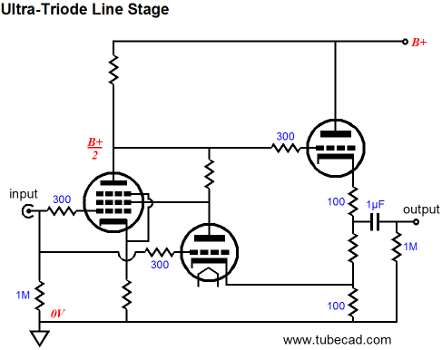
Because I have posted so little in the past few months, a lot of blog fodder has passed me by. For example, back in late December, an avid TCJer wrote to me asking about ultra-linear line-stage amplifiers, as he owns a huge collection of interesting 9-pin and octal pentodes (and pentode-triode dissimilar tubes, such as the 6AN8, 6AU8, 6BH8, and 6BM8) that are just sitting idle in his garage. He had discovered some of my past posts on this topic, such as the ultra-linear Aikido, which I covered in blog 69. He didn’t need a lot of gain and he wanted to experiment with different ultra-linear ratios, so I recommended the following circuit as a useful test bench and starting point.
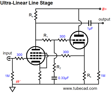
By varying the ratio between resistors, R1 and R2, the ultra-linear ratio is set. If resistor R1 is made equal to 0 ohms, the pentode functions as a triode-connected pentode; if resistor R2 is made equal to 0 ohms, the pentode functions as a pure pentode. In between these two extremes, resides ultra-linear operation, wherein the pentode’s screen sees an input signal that is out of phase with the signal presented to the pentode’s grid. Because the screen’s signal is in anti-phase, the gain realized at the plate is reduced, but the output impedance and distortion is decreased compared to pure pentode operation. The most commonly used ultra-linear ratios fall between 10% to 50% of the plate’s output signal. For example, if the plate swings a peak-to-peak voltage of 10V and the screen sees a peak-to-peak voltage swing of 2V, then the ultra-linear ratio is 20%.
Of course, soldering and de-soldering resistors is a small pain, so the following variation is welcome. 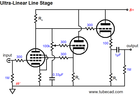
The potentiometer allows the ultra-linear ratio to be changed on the fly and the added cathode follower buffers the output. This design could be used an actual line-stage amplifier; but it would make me more than a tad nervous, as potentiometers are famous for becoming scratchy (I am always amazed how nonchalant so many solder slinger are about using potentiometers in their designs). In addition, I fear the huge voltage differentials that the two cathode followers will see at their cathodes and grids at start up, when the tubes are not conducting, but he B+ is already established—the grid of a 6SN7 should never be 300V more positive than its cathode. Two protecting diodes, however, will take care of that problem.
The pentode’s screen voltage will be slightly higher than its plate voltage, in the above circuit. Often we wish to use a substantially lower screen voltage. The easy workaround would be to place a resistor in parallel with the 0.33µF AC shunting capacitor. For example, a 100k resistor would halve the plate voltage.
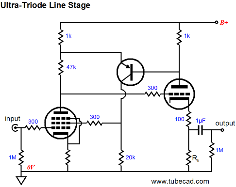
One liability to the above circuit is that it requires two triodes, while dissimilar tubes, like the 6AU8, hold only one pentode and one triode. (By the way, the pentode must be of the sharp-cutoff type, as sharp-cutoff means linear.) The following circuit uses only one triode and still offers a buffered output.
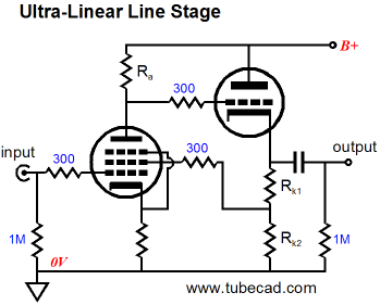
Cathode resistors Rk1 and Rk2 set the ultra-linear ratio for the screen. Once again the problem of exceeding a safe positive grid-to-cathode voltage at startup presents itself and the same adding-a-single-diode trick is the best solution. By the way, note that the pentode’s cathode resistor is not bypassed by a large-valued capacitor. Most pentodes will develop far too much gain as it is, so the un-bypassed cathode resistor will help reduce both the gain and distortion from the pentode. The following variation uses the two-resistor voltage divider to set the ultra-linear ratio and burn off some gain.

So which of these circuits would I build for myself? None of the above. I would prefer something along the following lines:
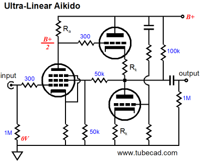
The Aikido cathode follower not only buffers the output, it also strips away much of the power-supply noise from its output. The two 50k resistors define a 50% voltage divider that sets the ultra-linear ratio to 50%. The 100k resistor offsets the current that the two 50k resistors will draw. Yes, two triodes are required, but greatly improving the PSRR is worth it. Besides, many fabulous pentodes are available one per tube envelope, such as the 6AC7, 6AK5, 6AU6, 6CW5, 6EJ7, 12BY7, 12GN7, and WE401. And most audio-worthy small triodes come two to the tube, such as the 6AQ8, 6BX7, 6DJ8, 6CG7, 6SN7, 12AU7, 12BH7, and 5687, just to name a few.
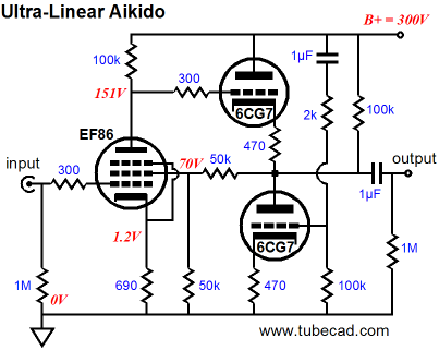
As any long-time reader knows, I like the widest possible array of design choices; but at the same time, I don't like getting lots of e-mail asking me to fill in the missing part values in schematics that I posted (as topological design examples). Thus, the above schematic, replete with parts values. (Or should it have been "complete with parts values," as "replete" means overstuffed? Time to check the dictionary.) The above values are derived from SPICE simulations, so your mileage may vary, as they say. This is the ultra-linear Aikido I would most like to build.
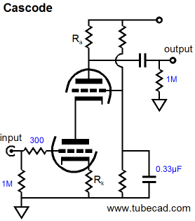
The cascode circuit was created to squeeze pentode-like gain from triodes, while still retaining the triode’s low noise.
The following is excerpted from the Tube CAD User Guide:
“CASCODE” is a contraction of “CASCaded triodes with
the gain of a pentode and the low noise of a triODE.” It is
built up of one triode in current series with another triode.
The bottom triode’s cathode is grounded and its grid is fed
the input signal, while its plate is connected to the cathode
of the top tube, whose grid is grounded. This loading of
the plate with a cathode prevents the bottom tube’s plate
voltage from moving very much in response to signal at its
grid, as the top tube cathode functions like a voltage
regulator made from a cathode follower. Nonetheless, the
bottom tube will experience variations in the current
flowing from its cathode to its plate, because of variations
in the grid to cathode voltage. The same would also hold
true if the triode were connected across a regulated power
supply, as a varying grid to cathode voltage would also
define a varying plate current in this arrangement. In the
Cascode circuit, this varying current through the bottom
tube must also flow through the top tube, as they are in
series. And as the top tube’s plate is loaded with a plate
resistor, the varying current defines a varying voltage across
its plate resistor, which yields the output voltage and gain
of this circuit, which can be considerable. Thus, “the gain
of a pentode.”
The circuit, furthermore, functions much like a pentode in
that its Miller Effect capacitance is very low, as the grid of
the bottom tube is shielded from the inverted amplification
at the top tube’s plate. Also like a pentode-based circuit,
the distortion from this circuit is higher than would have
been the case with only one triode. This is because the
bottom triode does not experience any of the linearizing
effects of running the triode in a closer approximation of a
constant current mode, as in the case of a grounded-
cathode amplifier with a large plate resistor. It differs,
however, from the pentode by the fact that there is no grid
current flowing into the top triode’s grid as there is with
the grid 2 of a pentode and by the fact that the noise is
lower than a pentode’s. Thus, “the low noise of a triode.”
The secret behind this circuit is that it is an elaborate
attempt to conserve as much of the triode’s
transconductance as possible. In a normal grounded
cathode amplifier, the plate load resistance subtracts from
the effective transconductance of the triode. The plate load
resistance added to the plate resistance (rp) and then
divided into the mu of the triode determines the
transconductance of the triode.
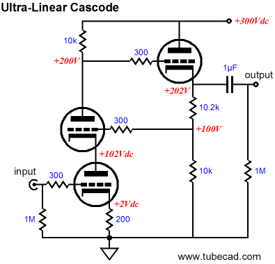
There, that saved me a lot of typing. Adding an ultra-linear flavor the cascode is easy, as the top triode’s grid functions much like a pentode’s screen. Back in the early 80s, I came up with the following circuit on my own.
I was quite pleased with the results and I eagerly showed the circuit to fellow tube-topologist at a tube club meeting. I discovered that I was not alone in coming up with the circuit, as two other club members had as well, but I was alone in thinking this topology worthwhile. The majority view was that the top triode offered so little effective transconductance, due to its huge effective cathode resistor made up of the bottom triode and its cathode resistor (Z = rp + [mu + 1]Rk), that feeding the top grid any negative feedback signal was a wasted effort; furthermore, they argued, it just made more sense to retain as much gain as possible in the cascode stage and then apply a global negative feedback loop across the entire amplifier.
I disagreed, arguing that often only a single gain stage is needed and that the ultra-linear cascode’s potential output voltage swing was greatly enlarged by the ultra-linear variation and that its distortion fell by more than the reduction in gain would seem to imply as being possible. If nothing else, I further argued, the DC feedback was a great help in keeping the cascode in line with design parameters; in fact, a DC-only self-biased cascode could easily be assembled. 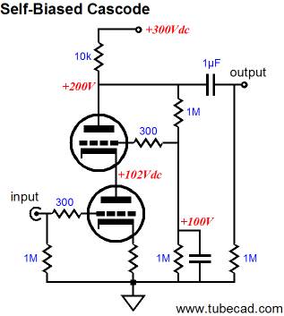
Recently, after perusing a few hundred tube-circuit-filled patents, I discovered that William Z. Johnson had patented the following circuit in 1987, US patent 4,647,872.
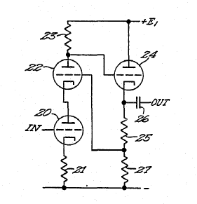
(I also remember seeing a prior patent that contained the same ultra-linear cascode concept, but I haven’t been able to find it again. In fact, I am sure that just about everyone who has been serious about tube circuit design has also came up with this topology on his own; it is an obvious analogy to the pentode ultra-linear topologies.)
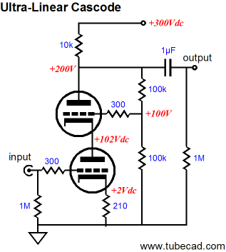
Filling the part values yields the following schematic:
All the triodes are of the 6DJ8/6922/ECC88 type. The above circuit presents at least two design problems: the cathode follower’s triode is sitting up at 200Vdc, so its heater will require its own floating power supply or heater winding; and the cascode’s poor PSRR remains mostly unchanged by the ultra-linear modification. The first problem can be solved by lowering the cascode’s plate voltage to no more than 150V; the second problem, by using an Aikido cathode follower. The following circuit shows what this marriage would look like.
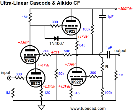
All the triodes can share a heater winding or power supply referenced to 75Vdc. The Aikido cathode follower’s top power-supply-noise-injecting resistor’s value is left unspecified, but my guess that it needs to be between 1k to 4k in value. Just from looking at the tubes and part values, my guess is that the gain would come in at about 50, which is far too much for line-stage amplifier, but would work beautifully in a phono stage or, maybe, in a microphone preamp.
We know that if the screen in a pentode sees a steady fixed DC voltage, the pentode will function as a pentode, with high gain and poor PSRR; we also know that if the screen sees 100% of the plate’s output signal, the pentode will function like a triode, with lower gain, distortion, and improved PSRR; moreover, we know that we can feed the screen some ratio of plate signal in an ultra-linear fashion. So at one extreme, we have pure pentode; at other, pure triode; and in between, ultra-linear. Now, what would happen if we fed the screen more than 100% of the plate output signal, say 130%? In other words, what would happen if we amplified the plate output signal, preserving its phase, but increasing its amplitude; and then we fed this bigger signal to the pentode’s screen? Ultra-supra-mega-triode operation? A reasonable assumption would be that the gain, distortion, and output impedance would drop further. An interesting idea, no? But how do implement such circuit?
The above circuit might be a move in the right direction. The added triode sees the same input signal that the pentode's grid sees, and the triode's cathode sees a small input signal from the cathode follower output stage. Both input signals combine to increase the triode's gain. Furthermore, these two input signal sources are in addition to the triode’s plate terminating into the pentode’s plate, which works to bootstrap extra gain from the triode. In other words, it shouldn’t be too hard to make the triode’s gain exceed the pentode’s, which is what ultra-supra-mega-triode mode would require.
The above circuit is a hybrid affair that uses a single PNP transistor to create the in-phase and amplified plate signal needed. Yes, the transistor will creep many out; and, yes, the transistor may introduce more distortion than its use cleans up, nonetheless such a circuit just may prove truly interesting. (And of course, a P-channel MOSFET could replace the PNP transistor and a long-tailed differential amplifier made up from PNP transitors could, and maybe should, replace the single transistor.)
First of all, I hope next time comes a lot sooner than last time. In addition, I hope to have a bunch of new PCBs and kits available by then. Until then, here is a sample of what coming:
and 
//JRB
|
|
|
|
Kit User Guide PDFs
Click image to download


E-mail from GlassWare customers:
Mr Broskie,
I bought an Aikido stereo linestage kit from you some days ago, and I received it just this Monday. I have a few things to say about it. Firstly, I'm extremely impressed at the quality of what I've been sent. In fact, this is the highest quality kit I've seen anywhere, of anything. I have no idea how you managed to fit all this stuff in under what I paid for it. Second, your shipping was lightning-quick. Just more satisfaction in the bag, there. I wish everyone did business like you.
Sean H.
And
Hi John,
I received the Aikido PCB today - thank you for the first rate shipping
speed.
Wanted to let you know that this is simply the best PCB I have had in my hands, bar none. The quality is fabulous, and your documentation is superb. I know you do this because you love audio, but I think your price of $39 is a bit of a giveaway! I'm sure you could charge double and still have happy customers.
Looking forward to building the Aikido, will send some comments when I'm done!
Thank you, regards,
Gary.
9-Pin & Octal
PCBs & Kits
High-quality, double-sided, extra thick, 2-oz traces, plated-through holes, dual sets of resistor pads and pads for two coupling capacitors. Stereo and mono, octal and 9-pin printed circuit boards available.
Designed by John Broskie & Made in USA
Aikido PCBs for as little as $20.40
http://glass-ware.stores.yahoo.net/
Only $19.95
to keep track of your
tube and part collection
TCJ My-Stock DB
TCJ My-Stock DB helps you know just what you have, what it looks like, where it is, what it will be used for, and what it's worth. TCJ My-Stock DB helps you to keep track of your heap of electronic parts. More details.
List all of your parts in one DB.
Add part Images.
One-click web searches for part information.
Vertical and horizontal grids.*
Create reports as PDFs.*
Graphs added 2D/3D: pie & bar.*
More powerful DB search.
Help system added.
Editable drop-down lists for location, projects, brands, styles, vendors and more.
*User definable
For more information, please visit:
|


