| John Broskie's Guide to Tube Circuit Analysis & Design |
08 May 2009 New: The All-in-One Line-Stage/Headphone Amplifier
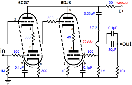
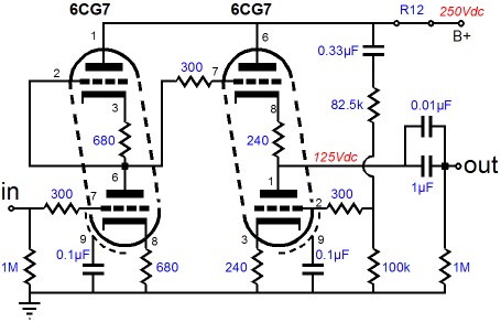
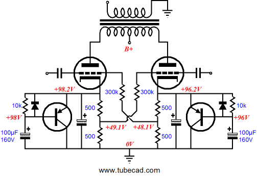
The photo above shows the new LSA/HPA board, but it makes the board appear smaller than it actually is, as the PCB is 6 by 10 inches, which is quite a handful. The LSA/HPA board was optimized for flexibility, allowing either a first-rate line-stage amplifier or headphone amplifier to be assembled. So, for example, in the photo above, you can see seemingly missing parts, but those parts were not needed for the headphone amplifier configuration. In other words, I built up a headphone amplifier on this board, which helps to explain the large coupling capacitors and the dissimilar input and output tubes. The 30µF, 250V, polypropylene coupling capacitors are made by Dayton and were intended for loudspeaker crossover networks. A long-time TCJer wrote to me, telling me that these were the killer coupling capacitor for headphone amplifiers. I bought a pair and tested them, finding his high appraisal pretty much on the mark. I had been using large, 47µF, 630V Solen coupling capacitors in my headphone amplifiers and while the Dayton capacitors definitely sounded better, they were not hugely better. On the other hand, I am sure they make the 250V Solens sound much weaker. (These capacitors wil be available at the GlassWare Yahho store.) I used 6CG7s as the input tubes and 6DJ8s as output tubes, with the output stage configured as a White cathode follower. In addition, I set a purposely low B+ voltage of only 140Vdc, as I wanted to run a heavy current through the output tubes, without exceeded their dissipation limits or excessively shorting their lives. The schematic that follows reveals the part values I used.
Does the major topological change stand out? Look at the top-rightmost resistor, the 150-ohm series resistor. Note how it no longer terminates solely into the output tube, but now encompasses the input tube as well. Why? After some experimenting, I found that this rearrangement further reduces distortion, always a worthwhile goal. Also note the small values for the 6DJ8 cathode resistors, only 49 ohms. This value insures a high current flow and a low output impedance. My primary headphones are the Sennheiser HD-650, which can sound bass-flabby with too high an output impedance. I know this from recent experience, as I have just built up a 12SX7-based Aikido headphone amplifier and, although it offers ear-pleasing midrange sweetness, its relatively high output impedance imparts a bloated bass to the HD-650s that I cannot abide. Of course, some would love the sound from this 12SX7 headphone amplifier, finding it just right. I have no problem with that, as what could be the goal of high-end audio other than individual pleasure. (I can think of a few snarky retorts, but I will bite my sharp tongue.) One workaround for flabby bass might be to use a seemingly too small coupling capacitor value, say 10µF, which might effectively flatten the bass hump, although I doubt it would do anything to improve the bass definition and it would certainly eliminate the deep bass. (By the way, for the last 30 years, I have been using big sub-woofers with my headphones. Why? Much of the impact that music can deliver is missing from headphone listening because our body misses the somatosensorial wallop that big drums dispense. Thus, along with big subs, the small-valued coupling capacitors might not be such a bad idea.) I have no real reason for pasting the above image of the new Sennheiser HD-800 headphones, other than I would dearly love to listen to them with my one of my tube-based headphone amplifiers. If this new model offers as substantial an upgrade from the HD-650 as is rumored, then a fantastic headphone and tube headphone amplifier setup could be readily put together. Sad to say, but they are out of my budget’s range (or is it my wife’s lenience?). Still, I get giddy just thinking about how sweet a sound would emerge from this pairing. So how does this new All-in-One Aikido sound as a headphone amplifier, albeit only paired with HD-650s? Marvelous, just marvelous. It strikes that right balance between tube sweetness and high definition. I have in the past built tube headphone amplifiers that dripped with sweetness, but lacked detail; and solid-state headphone amplifiers that delivered piercing detail, but frayed the nerves. One thing I immediately found impressive was the absence of the urge to turn up the sound level. In fact, for each recording, I was instantly able to set the volume control to the right value.
Loudness Distortion
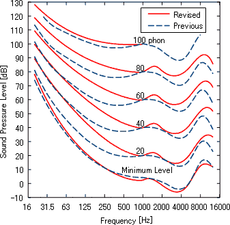
Sounds, on the other hand, change “color” based on sound pressure level, as the ear’s frequency response is not linear, mids beings much easier to hear than lows. So a change in volume is also a change in tonal balance. For example, a recorded whisper played back at high volume will not sound like a whisper—not just because it is loud—but because it will seemingly contain too much low-frequency content, whispers being thin, bright-sounding utterances. Yet a spectrum graph of the quiet whisper and its amplified reproduction would display the exact same frequency distribution. Thus, if we want to hear a tonally-natural amplified whisper, we must cut some of its bass first. Conversely, if we want to play back organ music at low volume settings, we must boost the bass to compensate for the perceived lack of bass. Obviously, this was the rationale behind the loudness control of stereos past. Yes, yes, I know that most loudness controls sounded terrible, being no more than just super bass boosters. Nonetheless, the motivation behind adding a loudness control is defensible, as music played back at low volume levels sounds weak and thin. But, once again, most loudness controls sound terrible. They lack subtlety. They muddy the deep bass. They are tied to the volume control, so they cannot be adjusted independently from the volume control. Thus, I once set about designing the best loudness control I could. The first roadblock I encountered was that the famous Fletcher–Munson curves are certainly famous, but not so accurate. But even when we use the latest set of equal-loudness-level curves, we realize that the old loudness control was incomplete, as it only worked in one direction: more bass with lower volume. It did nothing for the example of the magnified whisper not sounding tonally right. In other words, a truly useful loudness control must work in both ways, contouring the frequency to music (or sounds in general) played too softly or too loudly. For example, an a cappella singer played back at 100dB will not sound right, even if the loudspeaker and electronics are blameless. We need a loudness control that is independent from the volume control and that offers a flat position in the middle of its rotation and then a boost or cut in bass (and, to lesser degree, high frequencies). Such a loudness control would be more of a help for the average audiophile, as most audiophiles love cranking up the volume, often requiring a bass cut; whereas most music lovers are content to listen at low volume from kitchen radios, usually requiring a bass boost. Okay, back to the All-in-One LSA/HPA, with this headphone amplifier, I have a much better feel for what is the appropriate volume setting, much as when I experimented with live microphone feeds decades ago. My brother owned a pair of high-quality Shure microphones and I preformed a few interesting experiments. I ran long leads of cable out of the listening room to the living room, then to the backyard, where the two microphones sat in stands waiting for some sound to capture. In front of the microphones my brother and friends played acoustic guitar, sang, jiggled car keys, and spoke, while I was in the house listening to loudspeakers reproduce live sonic events. Amazing, just amazing. The sound was so immediate and genuine sounding that all recordings, whether on LP or tape, sounded absolutely compressed and canned by comparison. It was then that I realized that the recordings themselves were the weakest links in the audio chain. In addition, I found that I knew exactly what the right volume setting was; too much was definitely too much, just as too little was obviously too little. Why wasn’t this true with records, I asked myself, as the playback volume level could pretty much be arbitrarily, without the ear complaining, or, rather, all volume settings sounded equally off base.
Lower Volume Levels
Loud sounds that do not produce discomfort, let alone pain, can nonetheless cause damage to ear, if the sound persists long enough. The following table is from an excellent article, Preventing Hearing Damage When Listening With Headphones, from the HeadWise website.
By the way, I have a theory that many are listening to headphones at far too loud a volume setting these days because many are listening to MP3 files. What if the loss-full compression used to decrease the audio file size also compels a louder playback volume in an attempt to regain some of the thrown away detail? It seems to me that this would be a perfect PhD dissertation topic and an easy way to fifteen minutes of fame, if the results of a few simple experiments proved my hypothesis correct; let test subject set the playback volume for the same songs but with different levels of signal loss in the audio file format. Then, the media would go into hysterical old lady mode and the American government would outlaw low-resolution audio files and trail lawyers would be lining up at Mercedes dealerships, their pockets filled with cash from Apple, Sony, Microsoft, and the Moving Picture Experts Group founding members. When will the new All-in-One LSA\HPA PCB and kit be available? Soon, I hope. I have yet to create a user guide for it (it's going to be thick), but it should be fairly easy, as I can stitch together the two old user guides into one fat guide. How much will it cost? The PCB will sell for $59 USD; the full kit, I haven't done the math yet. I should mention that I had only 11 boards made (I am keeping one for myself), so they will not last long.
Enough Headphone Amplifiers!
Classic Aikido. The two 6CG7s offer a sweet, high resolution amplification and unity-gain output stage buffering. Resistor R12 is replaced with a jumper wire and smaller-valued coupling capacitors are used, along with a higher B+ voltage. How does the new All-in-One LSA\HPA sound as a line-stage amplifier? I do not know, as I haven’t configured it as one yet. In Fact, I may not bother, as I have heard the PS-1 and stereo 9-pin Aikido pairings many times before.
Now for something completely different...
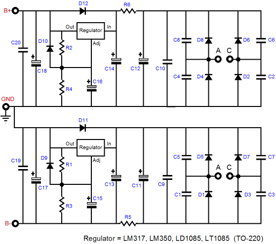
I have created small, 4 by 6 inch PCB that holds a low-voltage bipolar regulated power supply for solid-state use. Why? I have been experimenting with OpAmp circuits lately and I needed a killer low-voltage, bipolar power supply. The odd fact about three-pin voltage regulators is that no one makes a great negative regulator or, put differently, no one makes as good a negative regulator as the LT1085/LD1085 is as a positive regulator. So, I used two positive regulators. How is that possible? How do you get a negative regulator out a positive one? You don’t; you make two positive regulators and stack the outputs to create a bipolar power supply. The schematic below shows how.
Remember electrons only flow from negative to positive, so even a negative regulator, such as the LM337, is not going to make the electrons flow backwards. Also remember how relative electricity is. For example, imagine walking into an electronic store and asking for a negative 9V battery and being given an off-the-shelf 9V battery. You complain, telling the salesman that the battery is clearly a positive 9V battery and that you need a -9V battery. The old-timer barely contains his chuckle as he tells you that you are holding the battery wrong, that if you hold it the other way around, it becomes a negative 9V battery. (If there were such a thing as a negative battery, just how would you tell it apart from a positive battery?) Ok, why are there series resistors R5 and R6 in the circuit? These resistors define an RC filter with capacitors, C15 and C16. The resistors are 1 ohm in value and the capacitors are 6800µF/25V Nichicon audio capacitors, which means that the regulators see a pre-filter that defines a low-pass filter with a corner frequency of about 24Hz, which will greatly help filter away the high frequency ripple overtones, without losing too much voltage across the resistors. The B-PS-1 regulator also holds four large 3.3µF Wima MKP10 polypropylene capacitors to bypass the key electrolytic capacitors. The heatsinks are 2.5 inches tall and provide plenty of cooling for the two LD1085 regulators. The 25V capacitors allow a wide range of output voltages, from +/-5Vdc to +/-22Vdc. The rectifiers are same ultra-fast types used in all my low-voltage regulators. This regulator requires a power transformer with two secondaries, as it uses two four-diode rectifier bridges. In other words, a center-tapped secondary cannot be used. (The secret to understanding the regulator is to look at diode D11. On its left side is ground, with 0V; on its right side, something like +6Vdc. Thus, if a center-tapped secondary were used, the right side of D11 could never be greater than 0V and the regulator could not regulate.) The B-PS-1 regulator costs $69, which includes all the parts to populate the PCB, but not the power transformer. Fortunately, low-voltage power transformer with dual secondaries are easy to find.
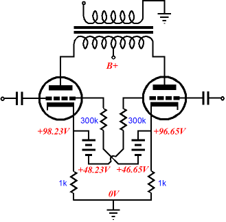
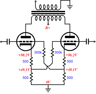
Garter Circuit Update The two-battery variation should have worked better was my firm conviction, so I reviewed the results and I saw that two variables had changed, the addition of the batteries and the halving of the cathode resistor value. The following circuit shows a garter circuit variation that uses two 50V batteries with 1k, not 500-ohm, cathode resistors (the B+ was increased to compensate for the increased cathode resistor(s) voltage drop). Now let’s compare results with the original Blumlein garter circuit shown below.
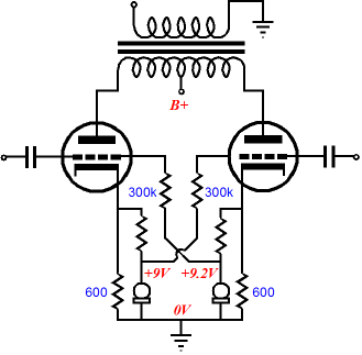
Now, the results match my expectations, as the circuit with the batteries does provide a tighter current matching. Wonderful, but where do I buy a 50V battery? You don’t, you could use constant-current sources instead.
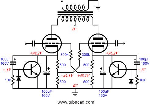
Chinese Cathode Cuffs Circuit
The Chinese-cathode-cuff circuit can be used with (or without) the Blumlein or my variations on the garter circuits or with just a single cathode resistor in an SE amplifier. No doubt it looks confusing at first. At idle, just imagine the NPN transistors are not there, as their bases are insufficiently positive to turn the transistors on. So why put them there? Their job is to limit the charge-building rectification effects during loud, sustained passages. But under idle or low-signal conditions, the added transistors just drop out of the circuit and do nothing. When the cathodes quickly starts charging up, however, the transistors turn on and apply the brakes to the cathode's climbing voltage. On the other hand, if long sustained high-wattage output is needed (organ music perhaps), the added transistors just drop out of the circuit once again, as the 100µF capacitors will slowly charge up and turn off the transistors. Without the this additional circuitry, all self biased power amplifiers face the problem of excessive cathode-bias voltage build up, as the amp moves beyond its class-A operating window. The added diodes are there to provide a discharge path for the additional 100µF caps, when the loud passage ends. See why this circuit is the equivalent of the Chinese thumb cuffs, with the toy, you pull your thumbs very slowly and they come free; pull quickly, you are caught. In the circuit, subsonic shifts in the cathode voltage are allowed, but audible changes in cathode voltage are not.
Exact same operating principle, but with with PNP transistors. Why? One advantage that PNP transistor would hold over its NPN brother in this circuit is that the tab is connected to the collector, which with the PNP transistor will be tied to ground, so less of a shock hazard exists (they might even be attached directly to the chassis, although I doubt that a heatsink would ever be needed).
Next Time
//JRB
*A change in lighting will result in a chromatic shift, as in the near dark, the eye’s color receptors turn blind, leaving only the grayscale receptors active. I even notice this when trying to read resistor color bands I dim light; in the dark, all resistors are 100k.
|
Kit User Guide PDFs
E-mail from GlassWare Customers And
High-quality, double-sided, extra thick, 2-oz traces, plated-through holes, dual sets of resistor pads and pads for two coupling capacitors. Stereo and mono, octal and 9-pin printed circuit boards available.
Designed by John Broskie & Made in USA Aikido PCBs for as little as $24 http://glass-ware.stores.yahoo.net/
The Tube CAD Journal's first companion program, TCJ Filter Design lets you design a filter or crossover (passive, OpAmp or tube) without having to check out thick textbooks from the library and without having to breakout the scientific calculator. This program's goal is to provide a quick and easy display not only of the frequency response, but also of the resistor and capacitor values for a passive and active filters and crossovers. TCJ Filter Design is easy to use, but not lightweight, holding over 60 different filter topologies and up to four filter alignments: While the program’s main concern is active filters, solid-state and tube, it also does passive filters. In fact, it can be used to calculate passive crossovers for use with speakers by entering 8 ohms as the terminating resistance. Click on the image below to see the full screen capture.
Tube crossovers are a major part of this program; both buffered and un-buffered tube based filters along with mono-polar and bipolar power supply topologies are covered. Available on a CD-ROM and a downloadable version (4 Megabytes). Download or CD ROM
|
|||||||||||||||||||||


| www.tubecad.com Copyright © 1999-2009 GlassWare All Rights Reserved |