| John Broskie's Guide to Tube Circuit Analysis & Design |
|
28 September 2008
Like the citizens of New Orleans, I expected much worse. The Big-Easy folk never bore Hurricane Ike’s full wrath; nor did I get the storm of angry e-mail against which I had braced myself, in the wake of my recent Ultrapath blog. In fact, not one reader complained. Instead, I received several e-mails with subject lines along the following lines: “Ultra-pathetic” and “Ultra-waste-of-time.” The sentiment was the same in all of them: “Thank God. I thought I was alone. Finally someone else has spelled out the obvious flaws in the Ultrapath circuit. Thanks.” Once again, my aim was not to slam the Ultrapath circuit, but to point out when shifting the bypass capacitor "ground" reference to the B+ works... and when it doesn't.
Tubes and Religion
Well, it looks like I just got promoted. I have been called a tube guru many times, which is not is not something I want to be called . (On the other hand, I have friends who would give anything—anything—to be called a maharishi or guru or sage or czar or….) But now I am being hailed as the American tube pope, "Der amerikanische Röhrenpapst John Broskie;" well, at least I am at the German HB HIFI website.
Then again, maybe every tube fancier in land of Luther is a Röhrenpapst, Still I think that, in my case, a humble tube monk would be much closer to the truth.
On to some more mundane issues...
24V Aikido Kits Well, I finally put together six kits of the 24V Aikido line-stage/headphone amplifier. These kits contain all that is needed to populate the PCBs:
Why only six kits? That is all the 6GM8/6N27P/ECC86 tubes I could gather. As I collect more of these amazing little tubes, I will offer more kits. For more information or to purchase, please visit the GlassWare Yahoo Store: http://glass-ware.stores.yahoo.net/ (Speaking of the 24V Aikido PCB, I plan on assembling a high-voltage version, using the same 24V PCB. This time, however, a high-voltage MOSFET and constant-current source will be used, along with four 6CG7s [or 6DJ8s]. I am keen to hear how it sounds with a B+ voltage of only 120Vdc. The big limitation will be the heatsinks, as they are only good for about 5W of dissipation, which will limit the amount of idle current through the solid-state, unity-gain output stage. In other words, 5W/60V = 83mA. And as I fear getting anywhere near dissipation limits, I'll only run 50mA through the MOSFETs, which should still be plenty for my Grado SR225s and far more than my Sennheiser HD650s require.)
The 24V Aikido line/headphone amplifier needs a 24V to 26V power supply. Wallwart transformers and desktop switcher power supplies are readily available, but for the best performance nothing beats a good linear voltage regulator. The above photo shows a blank and populated H-PS-1 PCB. The H-PS-1 is a simple low-voltage regulator. You need only hook up a powrer transformer and the H-PS-1 will rectify and regulate the AC voltage into smooth, stable DC. This little regulator can put out up to 2.5A and it can deliver an output voltage that ranges from +5V to +25V. This power supply is perfect for the 24V Aikido line/headphone amplifier.
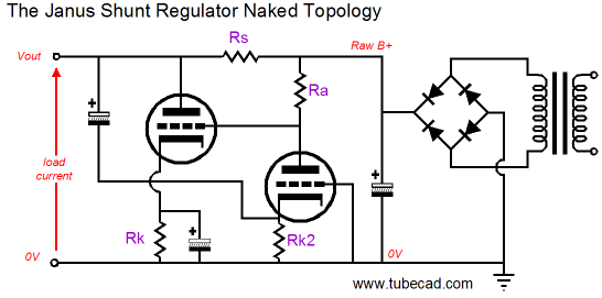
Janus Regulator Kits The Janus shunt regulator made its first appearance in 2007, at the end of Blog 112 and in the middle of blog 117. In a nutshell, the Janus shunt regulator uses both feedforward- and feedback-based shunt regulation to reject both the rectifier-induced power-supply noise and the signal-induced power-supply noise from its output. In the simplified circuit shown below, we see the rightmost triode doing the double duty of voltage dividing the raw power supply ripple by a fixed amount and by amplifying the error signal at the regulator's output, and then passing the correction signal to the leftmost triode's grid, which then the leftmost triode inverts the input signal at its plate, thereby nulling the error signal at the regulator's output.
The new Janus regulator PCB holds the following implementation of the regulator.
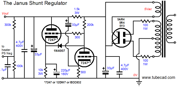
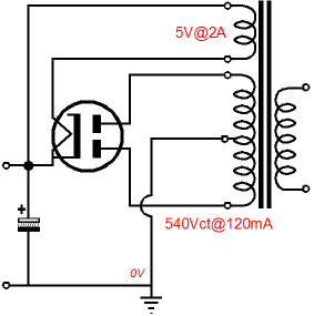
Note the use of a tube rectifier, either a 5AR4, 5R4, or 5Y3. I figured that since the Janus regulator uses vacuum tubes, why not go all tube. Also note the lack of DC voltages in the schematic. This implementation of the Janus regulator was designed to deliver between +250V to +300V worth of B+ voltage. The Janus regulator is not a DC voltage regulator, as it cannot maintain a fixed B+ voltage; instead, it works to eliminate any AC perturbations on its output voltage. In this way it is similar to a large inductor-filled power supply that bucks quick changes in output voltage, but allows slow DC voltage to vary with the wall voltage variations. In other words, with the Janus regulator, the output voltage will depend on the input voltage and the current drawn through the key series resistor, which in this example is 1500 ohms. For example, given a raw power supply voltage of +350Vdc after the rectifiers and a current draw of 28mA (plus 5mA through the leftmost triode), the output voltage will be +300Vdc, as 33mA against 1500 ohms equals a voltage drop of 50V. In other word, do not expect this realization of the Janus circuit to power a KT88-filled power amplifier. The limiting factors are the 3W 1500-ohm series resistor, the 4.7µF/400V film input and output power-supply capacitors, and leftmost triode’s plate dissipation. The power transformer’s selection is somewhat critical, as too high a primary voltage will create too high a B+ voltage. Unfortunately, most high-voltage power transformers are truly high-voltage. I used an Allied Electronics power transformer 6K56VG, with a 110-120V primary, 50/60HZ, and secondaries that offer 540VCT @120DCMA, 5V @3A, and 6.3V @3.5A. It was made in Canada (and looks exactly like a relabeled Hammond transformer).
By the way, the old IAR Wondercaps are used only because I had them on hand—besides they actually sound quite good in this application. The Janus PCB also holds a low-voltage regulator circuit for the heaters and this second regulator can be seen clearly in the following photo. I configured the heater regulator to put out 12Vdc, which is quite a feat, considering the 6K56VG power transformer only holds a 6.3Vac heater winding. The trick lies in using a voltage-doubler rectifier circuit that doubles the 6.3V to 12.6V, but at half the current.
The math behind heater power supply rectification cannot be ignored—although it is almost universally ignored by most solder slingers. For example, given a heater winding with a 3A rating, how much DC current can it deliver? Is it 4.2A or 3A or 1.7A? The correct answer is also the most depressing one, 1.7A. When a secondary sees a full-wave rectifier circuit, the resulting DC voltage is higher than the AC voltage presented to the rectifiers. Why? The answer lies in how AC and DC voltages are measured.
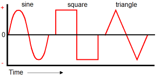
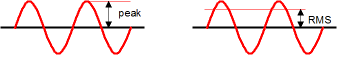
Bear in mind that AC voltage means a varying voltage and how it varies makes a big difference. For example, sinewaves, square-waves, and triangle-waves shown above all give a different AC voltage reading, although each develops an equal peak voltage. Why not just take the peak voltage as the AC voltage? We could and we would, if we were only interested in peak voltages, but usually we are interested in the resulting power dissipation into a resistance that he AC voltage produces. For example, let's consider the differences when we plug a light bulb into an AC socket or a tube’s heater across a heater winding. In these examples for example, the three different AC waveforms would produce three different amounts of heat, although each produced the same peak voltage. With sinewaves, the AC voltage equals the peak voltage divided by the square root of 2, i.e. 1.414. Thus, a 10Vac sinewave peaks at 14.14V; a 6.3Vac, 8.9V. In other words, a sinewave that peaks at 14.14V will produce the same amount of heat in a resistance as a 10Vdc voltage source would produce in the same resistance; thus, we label the 14.14Vpk sinewave as being 10Vac.
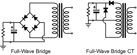
In the full-wave rectifier circuit, there are two rectifier-induced voltage drops, usually about 1V each with solid-state rectifiers; with tube rectifiers, about 10V to 40V. Of course, what comes out of a rectifier circuit is only unidirectional pulsing voltage and it is the power supply filtering capacitors that create something closer to a steady DC voltage. So, in the example of a 10Vac winding and solid-state rectifiers, the rectified DC voltage hovers around 12Vdc; with 6.3Vac winding, about 7Vdc. Observe that since we have lost voltage across the rectifiers, the resulting DC voltage could never meet its AC power rating, as we have introduced losses in the rectifiers. Additionally, the resulting DC voltage is higher than the nominal AC voltage, which also prohibits the full AC current rating to be obtainable, as the AC current against the DC voltage would exceed the transformer’s AC power rating. For example, a 10Vac winding that is rated for 1A can deliver 10W into a resistive load, but it cannot deliver 12Vdc and 1A (12W) into a resistive load, as free lunches and perpetual motion exist only in the political realm. So, how much current can the 10VA, 10Vac, 1A winding deliver once it has been processed by a full-wave rectifier circuit? The answer is about 0.56A. The math is simple, with a full-wave rectifier circuit, the DC current limit is equal to the AC-current rating divided by 1.8; with a full-wave-center-tapped rectifier circuit, the DC current limit is equal to the AC-current rating divided by 1.2.
Okay, now I will explain why just about half of all tube-loving solder slingers get easily confused about rectified current ratings: inconsistent current rating methodologies. If you look at the specs for the power transformer I used, 540VCT @120DCMA, 5V @3A, and 6.3V @3.5A, the high-voltage secondary's current rating assumes a full-wave-center-tapped rectifier circuit, but the 5Vac and 6.3Vac current ratings assume no rectification and just a bare resistive load. In the following schematic, as an example, the power transformer is labeled with both AC and DC current ratings.
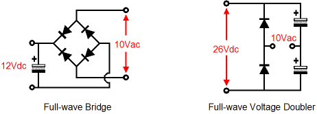
The transformer manufacturers are trying to be helpful, as in the old days, few ever dreamed of applying DC to their tube heaters and filaments. Times have changed, but the old rating system remains in place. On the other hand, a power transformer intended for non-tube use is never rated in rectified terms, as the transformer manufacturer cannot guess what sort of rectifier topology, if any, will be used, so only the AC current rating is given. A huge percentage of the e-mail I receive asking for my help in fixing a troubled piece of tube equipment could be eliminated, if everyone knew the preceding power-supply-design calculations. The trap of underestimating the heater demands (and the rectification limitations) is an easy one to fall into. For example, you would think that 3.5A heater winding should have no problem heating four 6SN7s, as four 6SN7 heaters in parallel draw only 2.4A. In fact, 6.3Vac @ 3.5A, once it is converted into DC, can only power three 6SN7s. Now, we can return to the voltage-doubler circuit. The two rectifiers and two filtering capacitors create voltage-doubler that can turn 10Vac into about 26Vdc.
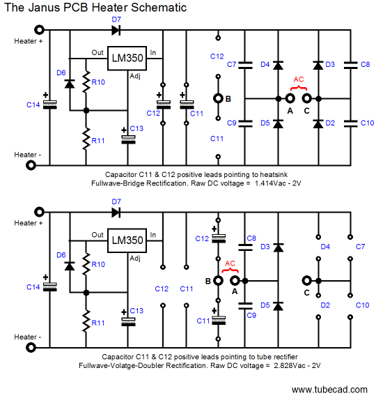
So how much current can the voltage doubler circuit wring from a transformer secondary? Well, we can start by halving its nominal AC rating and then dividing by 1.8. thus, for example a 1A current rating will yield 0.28A into a resistive load; 3A, 0.83A. In other words, the 6.3Vac @ 3A winding, once run through the voltage doubler, will not power four 6SN7 or four 12SN7. It will, however, power four 12AU7s or 6DJ8s quite nicely—powering four 6SN7s will require a 6.3Vac @ 4.5A winding. Below is the heater power supply schematic used on the Janus PCB. As can be seen, the power supply can accept either full-wave bridge rectifier circuit or a full-wave voltage doubler rectifier configuration. When used as a full-wave bridge rectifier circuit, the two power supply filtering capacitors are oriented with their positive leads pointing to the top of the PCB, where the heatsink sits; configured as a voltage doubler, these capacitors are rotated 90 degrees clockwise, so the positive leads point to the right edge of the PCB.
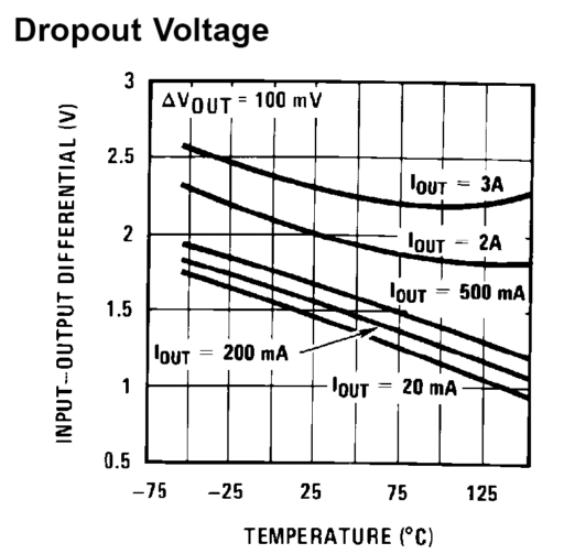
The LM350 is very much like a 3A upgrade of the famous LM317. The downside to this device is the relatively high minimum-voltage-differential voltage, "dropout voltage" in other words. The dropout voltage never exceeds 2.5V and is only 2V at 2A and 25c, but in a heater power supply getting a healthy amount of headroom is often difficult or impossible with most power transformers that are intended for use with tube gear. For example, a 6.3Vac winding yields about 7Vdc after rectification, which would voltage starve the LM350 in a 6.3V regulated power supply.
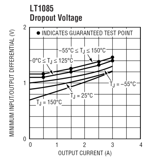
Thus, my almost universal recommendation to build a 12.6Vdc (or just 12Vdc) regulated power supply whenever possible, as the rectifier voltage drop consumes a smaller percentage of the raw DC voltage. For example, 12.6Vac becomes about 15.8Vdc after rectification, which would yield a 3.2V voltage differential across the low-voltage regulator. In addition, the heater wires can be thinner with half the current flowing them over the 6.3V power supply. Now, we have been assuming that the solid-state rectifier only loses about 1V voltage loss, but some audiophile-endorsed rectifiers can drop much more voltage, particularly the HEXFRED soft-recovery rectifiers. Moreover, the wall-voltage can drop an easy 10Vac during peak demands. (Where I live in sunny California, the month of August was marked by my uninterruptible power supply, aka UPS, clicking on and off constantly and just about every fellow audiophile I know locally complained that his system sounded bad last month.) In other words, mild brownouts can force the low-voltage regulator out of regulation by voltage starving the regulator. For example, if the wall-voltage drops by 10%, then the raw DC voltage presented to the power supply rectifiers will also drop by 10%, but the output voltage and rectifier voltage drops remain fixed. In the example with a 12.6Vac winding, the AC voltage presented to the rectifiers will be 11.34V and, after rectification, only 14Vdc will be available, so a 12.6V regulator output voltage will leave only a 1.4V voltage differential across the regulator; not enough, in other words, at least for the LM350. The LT1085, on the other hand, can still maintain regulation with a 1.4V voltage differential.
The downside to the LT1085 is that it costs about ten times more than the LM350. But the extra expense is cheap in terms of the hassle of trying to fix a low-voltage heater that has fallen out of regulation. UPDATE The Janus Regulator now comes with the LD1085, instead of the LM350.
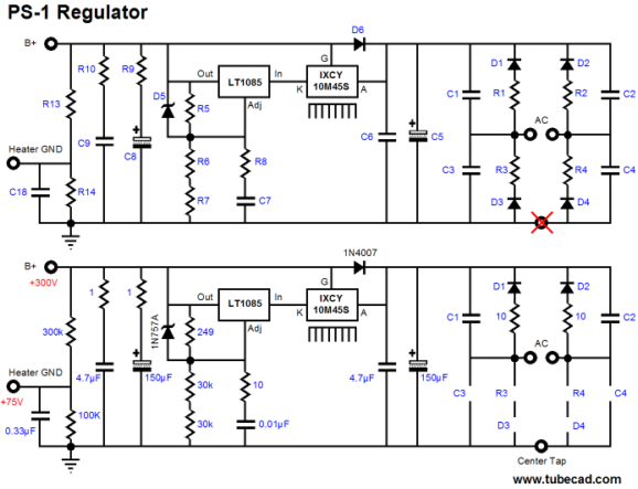
All-Solid-State, High-Voltage and Low-Voltage Regulator I have much to say about this circuit, but I have to stop writing, lest my fingers fall off. But I will leave you with the following schematic to hold you until next time. (The PS-1 PCB holds the exact same low-voltage heater regulator as the Janus PCB shown above.)
Next Time
//JRB
|
E-mail from GlassWare customers:
And
High-quality, double-sided, extra thick, 2-oz traces, plated-through holes, dual sets of resistor pads and pads for two coupling capacitors. Stereo and mono, octal and 9-pin printed circuit boards available.  Aikido PCBs for as little as $20.40 http://glass-ware.stores.yahoo.net/ Only $19.95
Download or CD ROM www.glass-ware.com
|
|||


| www.tubecad.com Copyright © 1999-2008 GlassWare All Rights Reserved |