| John Broskie's Guide to Tube Circuit Analysis & Design |
07 April 2008
More Circlotron Circuits
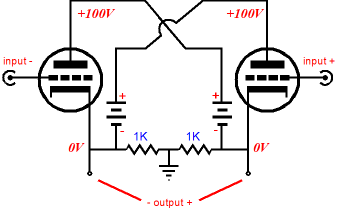
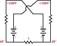
If both cathodes sit at 0V, then no current flows through the two resistors (or through an external load). When this output stage is putting some power into the load impedance, these two resistors will see a voltage differential and will conduct current and dissipate heat, although not much heat. For example, with a constant 100W into an 8-ohm load, each 1k resistor will dissipate only 0.2W. On the other hand, if one of the triodes shorts from cathode to plate, the full 100V will be developed across both resistors in series, so each resistor would then dissipate only 2.5W. Interestingly enough, I have seen commercially made Circlotron power amplifiers that used huge, high-wattage 1k resistors. Why? My guess is that there is some confusion over what these resistors do in the circuit. Ready for this? I once saw a circuit for creating phi (magic) energy from a Circlotron-like topology, as shown below.
The idea was that the 1-ohm resistor actually did see a current flow, even in the absence of a voltage differential across the resistor. It was believed that because two opposing streams of current flowed through the 1-ohm resistor, they cancelled out any voltage drop across the resistor; and that having two 1A streams of current flow against each other created a bunch of excess “phi” energy, which would radiate out to the benefit of the pot-smoking world. (Don’t laugh, it’s got be class-A, remember what the glossy ads say.) The same source also showed a passive phi-energy generator that consisted of a thick sheet of copper rolled and flexed into an arc and held in place by thick nylon belts. The idea was that the stressed metal generated phi energy and the arc shape allowed it to be focused much as a parabolic mirror would. When I stopped laughing, I pointed out that the bottom floor of every skyscraper must be chockfull of phi energy, as the weight of the building produced a compression stress on all the steel beams, and most so at the bottom of the building. Sad to say, but many audiophiles are much closer to New-Age space cadets than they imagine. Remember Peter Belts and his fantastic discoveries. Speaking of which, it would make a great book (or website) that chronicled the history of whacked audio nonsense. For example, I remember reading in the late Hi-Fi Answers magazine from England that a book’s number of pages influenced its sonic contribution to the listening room it found itself in and that either an odd or even number of pages made all the difference. Okay, here on planet Earth, let’s get back to tube circuits. The two-resistor voltage divider is not essential, as it could be replaced by a center-tapped inductor, as shown below.
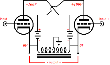
Grounding the center-tap also places the signal reference at the midpoint between the two outputs. Moreover, if a perfect inductor were used, no heat would be dissipated by the inductor, even if the amplifier were putting out 1kW into an 8-ohm load. Unfortunately, real inductors use real wire and hold real metal cores, so the wire’s resistance and the core’s losses due to hysteresis and eddy currents will generate heat. But our aim here is not to find a more-expensive substitute for the two 1k resistors, but a conceptual steppingstone to the next circuit shown below.
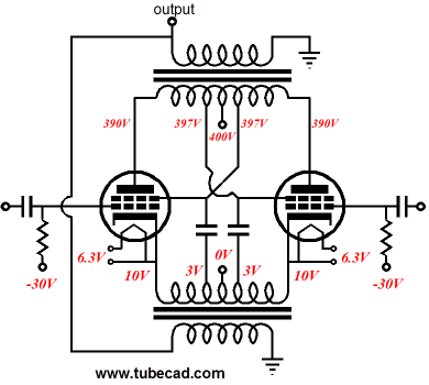
The Circlotron shown above uses an output transformer to couple to the external load and it still uses the two-resistor voltage divider to reference the input signals, although a center-tapped primary would also work. Below, we see the AC voltage relationships in the output stage.
Now let’s make a big jump to using two output transformers, each holding the same winding ratio, as both will see the same AC voltages and current flows and impedances. The two secondaries are wired in parallel, so as far as the triodes are concerned, the same load is presented as in the first transformer-coupled example (assuming the same output transformer is used).
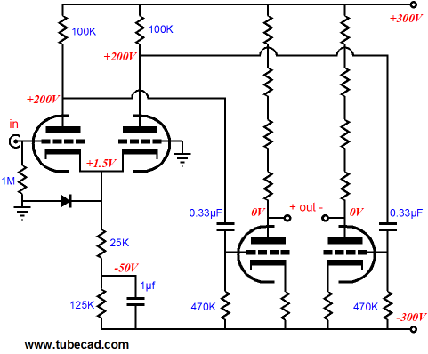
Now we get rid of the two floating power supplies and replace them with two large-valued capacitors and a single, ground-referenced power supply. (Center-tapped output transformers are necessary.)
Notice that the AC voltage relationships are the same within the output stage as they were with the single output transformer and the two power supplies.
On the plus side, we now can use a single power supply (perhaps tube-rectified) for not just one channel, but for as many channels that we wish to add: two, three, four…. In addition, we can now use first-rate output tubes, such as the 2A3, 6L6, 12B4, 211, 845, 300B, EL34, EL84, KT88…rather than being stuck with the clumsy 6AS7. Nor do we have to fear losing our expensive loudspeakers when a tube shorts out, as the output transformer will save the speakers from catching on fire. On the negative side, we retreated from OTL, which holds a small marketing cachet, which is somewhat offset by the fear of losing one’s loudspeakers in a mishap. Second, we have two output transformers instead of one to deal with. This is actually an advantage in my eyes, as we can get 40W from two 20W output transformers in parallel, but it is easier to find great low-power output transformers than high-output transformers and it will be easier to hide inside the chassis two smaller output transformers than one large one. Third, we have to use separate heater power supplies for the output tubes, as each has a big-voltage-swinging cathode, which would run up against the fairly low cathode-to-heater voltage limit (with DHTs, that voltage limit is 0V). Still, small 6.3V/2A power transformers are readily available, so this is not a big negative. Finally, we have to come up with two large-valued cross-coupling capacitors to take the place of the two power supplies that would otherwise be used.
Floating Power Supplies Now we get to the interesting part: Why bother with the added complexity of two output transformers and the two large-valued cross-coupling capacitors? Why not just stick to the conventional transformer-coupled push-pull amplifier?
If you plan on running your conventional transformer-coupled push-pull amplifier in pure, honest-to-goodness class-A, then the added complexity is probably not worth it. On the other hand, if you plan on getting a few years of life out of your output tubes and you don’t want to add to tube-induced-living-room warming, then class-AB is the best choice and this variation on the Circlotron is a good idea. Why? With conventional, class-AB, transformer-coupled, push-pull amplifiers, we have the problem of snapping primary windings. In other words, as one output tube turns off, it effectively lets go of its side of the primary, which causes half of the primary to left flapping in the void—never a good idea with any inductive circuit. This is why we have to be careful where and how we use a fuse with a choke-filtered power supply, as a blown fuse can instantly unload an energized inductor. Now, think about it, a capacitor stores an electrical charge, which can easily prove dangerous, if shorted; whereas an inductor stores energy in the form of flowing current and can prove dangerous, when the circuit is opened, as the stored energy must be released somehow. That somehow usually takes the form of a big spark, as the voltage must climb towards infinity because the current has fallen to zero. Sometimes the spark occurs inside your output tube or other amplifier parts, depending how the circuit is arranged. Well, returning to power amplifiers, in the two transformer Circlotrons, both primaries always have something to bite on, as the crisscrossing capacitors effectively place both primaries in parallel with both output tubes, so neither winding is ever left flapping, even as one tube ceases to conduct. Additionally, the output stage is configured as a modified cathode follower output stage, so we can expect the secondary signal to be both clean and very low in output impedance. Unfortunately, nothing comes without a price, so we must pay in the form of a fairly large drive signal for the output stage. Precisely how much drive voltage? A good starting point is the cathode voltage swing and the absolute value of the negative bias voltage added together. And this drive signal must be balanced. In other words, we need to build an electrostatic headphone amplifier of sorts to drive the output stage.
Dynaco ST-70
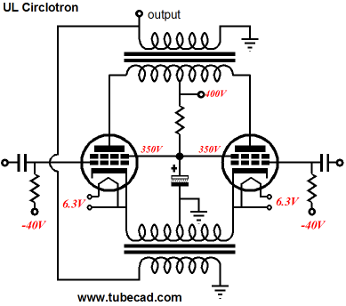
With triode-connected EL34s, we would get about 15W of super-sweet output; ultra-linear-pentode connected EL34s, we should expect more watts, but not the full 35W of the original—we will come to this aspect later. This raises the issue of what to do with the ultra-linear taps on the output transformers. One idea would be to use them, but not in the way that Dynaco had intended, as shown below. Leaving out the the two large-valued cross-coupling capacitors, we can see the UL connections more clearly.
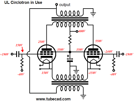
It doesn’t look right does it? Why are the ultra-linear connection cross coupled and why each output tube’s screen attached to the wrong transformer tap? Actually, nothing is wrong with the configuration shown above. Below we see what the voltage relationships look like as we take an AC snapshot of the amplifier putting out full power, with the left pentode fully on and the right pentode completely cutoff. The ultra-linear taps occur at 33% of the primary winding.
Note how much voltage is developed across each pentode and what the cathode-to-screen voltages are in the above schematic. Now, compare these values to the altogether conventional ultra-linear, transformer-coupled, push-pull amplifier shown below.
See how all the voltage relationships remain unchanged: the left tube sees a 0V cathode-to-grid voltage, a 100V cathode-to-plate voltage, a 300V cathode-to-screen voltage; and the right tube sees a -80V cathode-to-grid voltage, a 700V cathode-to-plate voltage, a 500V cathode-to-screen voltage. Still don’t see it? Well, lets move the negative probe of our voltmeter to left output tube’s cathode and retake all the voltages from this new reference, as shown below.
Our eyes may not like it, but the voltage relationships are the same nonetheless.
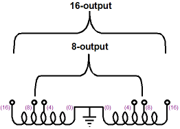
Harsh Reality In the Circlotron configuration, running under class-AB, each output tube "sees" the entire primary winding as a load, not just half of it; thus, the Circlotron sees the full primary impedance, not just one fourth of it. In terms of distortion and output impedance, this is wonderful; but in terms of peak power, it is not so good, as the four-times bigger impedance will greatly reduce the potential current swings. If you are using 4-ohm speakers, then the two secondaries can be placed in parallel, but the speakers must attach across the 0- and 16-ohm taps. If you are using 8- or 16-ohm speakers, then the two secondaries must be placed in series, with the speaker spanning the two 8-ohm or 16-ohm taps.
With the lower reflected impedance, two KT88s should put out closer to 40W, maybe even more. I am sure that some will note that I left off adding the obvious 4-ohm arrangement of spanning both of the old 4-ohm taps. The better route is to place both secondaries in parallel and using the full winding to attach to a 4-ohm load. Why? Both arrangements yield the same winding ratio, but the parallel windings will present half the DCR that the series arrangement imposes. (Besides, I don't like windings flapping in the void.) Now, I know that many just cannot get their brains to twist around winding ratios, reflected impedances, voltage ratios, and current ratios. Unfortunately, understanding just what a transformer can and cannot do is critical to designing tube-based power amplifiers. The secret is to never forget that the ideal transformer neither creates or destroys energy. In other words, if you put 100W into the primary, you cannot get 200W at the secondary. If the secondary's current flow is twice the primary's, then the secondary's voltage swing must be half that of the primary. Speaking of ideal transformers, I have assumed ideal transformers throughout, but real transformers hold DCR-laden windings, which will alter the seemingly exact voltages presented so far. For example, below is what might actually end up working in reality:
Another potential clash with reality is finding enough space on an ST-70's small chassis, as 630V cross-coupling capacitors should be used and they are not small. What value should they be. I am not sure, but 20µF would be a good start.
Creating Ultra-Linear Without UL-Taps
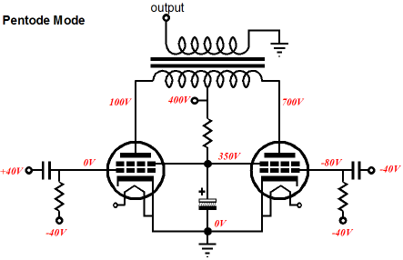
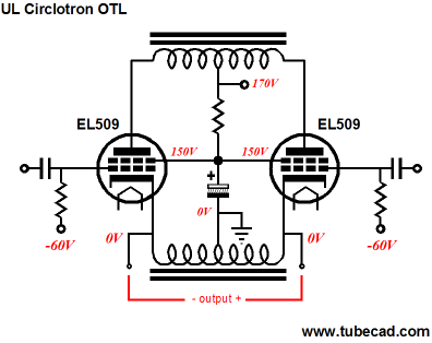
Above, we see the voltage relationships of the amplifier putting out full power, with the left pentode fully on and the right pentode completely cutoff. Note that the cathode-to-screen/G2 voltage is the same for both tubes, at idle, at full-power out. In the ultra-linear-configured amplifier, the cathode-to-screen voltage differ between tubes, as the plates swing in opposite directions. In the triode-connected amplifier, the plate-to-screen voltage for each tube is held constant, but the In the ultra-linear-configured amplifier, the cathode-to-screen voltage swings up and down with the plates swings.
The above circuit shows how we get ultra-linear operation from non-UL-tapped output transformers. Both screens connect to the same ground-refenced 350V connection, but each tube sees a different cathode-to-screen voltage, as the amplifier delivers power into a load.
Once again, we see the left tube fully on and the right tube fully off. Note the cathode-to-screen voltages and compare them to those at idle. Effectively, the left tube's screen has swung negatively by 150V (half of the plate swing) relative to the cathode; the right tube's screen has swung positively by 150V (once again, half of the plate swing) relative to its cathode. In other words, we have created a 50% UL tap out of thin air, except for the common screen resistor and shunting capacitor, of course. (I know that many are going to balk at not having their favorite UL ratio, 33%, 20%, 15%...but sometime you have to take what you can get.)
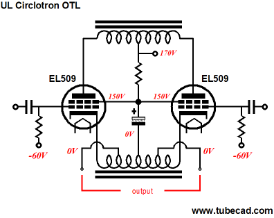
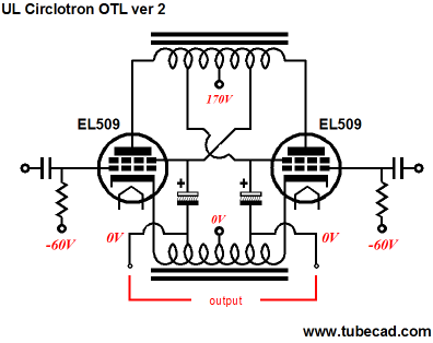
Now, imagine returning to Circlotron OTL and applying the same UL technique. Such an amplifier could be built using fairly low-voltage parts and it would certainly deliver more power into speakers than the same amplifier with triode-connected pentodes would. Of course, we could add two more taps to the bottom choke and get much better performance, as the load impedance would be much better matched to the tube's impedance.
Oh la la, I like the look of this output stage. If the speaker taps span 50% of the bottom inductor's winding, the reflected load impedance to the output tubes will be four times greater, which will make for a much more suitable loadline. Is it really an OTL? Good question. Big chokes look like big chokes, but the big difference is found in the tapped choke's ability to pass DC (say an output tube shorts from cathode to plate), something no transformer can do. Beside, if you can get away with labeling all Circlotron amplifiers as class-A, calling this amplifier an OTL is easy. Of course, now that we have added some extra winding taps to the bottom inductor, why not add them to the top inductor as well? Now we are back to a UL configuration similar to the transformer versions shown before.
By the way, two inductors could share the same core; in fact, an R-core dual-winding inductor might be the best choice.
Next Time
//JRB
|
Now accepting Support the Tube CAD Journal & get an extremely powerful push-pull tube-amplifier simulator for TCJ Push-Pull Calculator
TCJ PPC Version 2 Improvements Rebuilt simulation engine *User definable
Download or CD ROM For more information, please visit our Web site : To purchase, please visit our Yahoo Store:
|
|||


| www.tubecad.com Copyright © 1999-2008 GlassWare All Rights Reserved |