| John Broskie's Guide to Tube Circuit Analysis & Design |
22 February 2008
TCJ Attenuator User Guide
Back to the Future What could explain such a re-examination and re-adoption of the push-pull amplifier?
One obvious problem that all flea-power-amplifier owners face is finding the right loudspeakers. If you only have 2 to 5 watts to play with, then the list of acceptable loudspeakers truncates quickly. For example, I love Magnepan loudspeakers, but I also know that an 85dB/2.83V-efficiency, 4-ohm loudspeaker must be powered by at least a 50W power amplifier, not a 5w single-ended amplifier, no matter how dulcet. And those who still love the old Apogee line of ribbon loudspeakers know that their favorite loudspeakers require closer to 300W to frighten the mice in the walls. And let’s be frank, even when our loudspeakers are high-efficiency designs, lots of power—like lots money—is deeply satisfying. The thought tormenting most owners of flea-power-amplifiers:“If only I had a few more watts to wield then I would be happy.” In addition, I am sure many have had it with constantly practicing safe listening, the audiophile preoccupation with observing sonic safeguards, such as the exclusive listening to subdued music at low volume levels, so as to avoid power amplifier clipping and its attendant aural nastiness (and the resulting listener melancholy). Thus, it isn’t all that surprising that the greater power output offered by push-pull amplifiers can easily draw listeners back to them. Still, while I cannot deny that the push-pull amplifier's offer of greater potential power is the grand, apple-sweet temptation that dangles invitingly before the audiophile, but something else, something beyond just more watts must be contributing to this new and seemingly altogether favorable reassessment of push-pull designs. Somehthing is odd about all this fuss. First of all, it’s not supposed to work this way, as the saying goes: Once you have drunk of brandy, you can never go back to milk. Yet, many are not only going back to milk, but to the watery, non-fat kind. How can that be? No doubt part of it is that not all brandy is cognac. Haven't we all witnessed and marveled at the brisk sale of poorly-designed and obscenely over-priced single-ended amplifiers in the past decade? All too often, these new single-ended amplifiers were not any better than the old push-pull amplifiers they were meant to replace. But let's be even more frank: it’s all too easy to get bored. We weary of the same old sound and we long for something new—even if what is new isn’t any better than the old. In audio, like in clothing fashion, new is always better, no matter how silly or unattractive. I am waiting for cobweb and lead-foil coupling capacitors to be the new hot, must-have component; or how about titanium speaker cable—if it was good enough for the Terminator cyborg, why not your loudspeakers? How’s this for a T-shirt-sized slogan:
Aikido Single-Ended-to-Balanced Topology
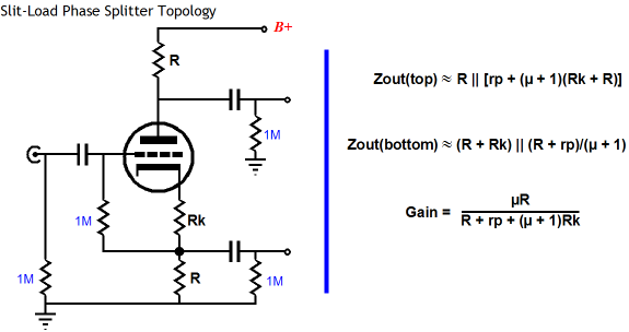
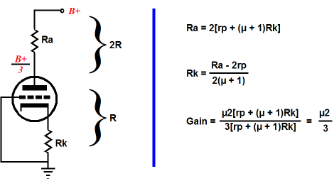
Converting a single-ended input signal into a balanced signal does not take much. In fact, a single triode per channel is all that is needed. The split-load phase splitter is amazingly simple and effective. Fundamentally it is nothing more than just a grounded-cathode amplifier with a cathode resistor equal to the anode resistor in value. Because both resistors see the exact same current draw, both being directly in series with the triode, both resistors will see a matching signal imposed across their leads. But as the resistors are terminated at different ends, the signals are out of phase with each other.
Much has been said about the mismatched output impedances offered by this phase splitter’s two outputs. And it is true that the two outputs do differ greatly in output impedance, with the cathode output offering a much lower output impedance than the plate output. but as long as both outputs are—simultaneously—loaded by the same load, both in terms of resistance and reactance, the two outputs manage to track each other about as perfectly as anything can in the realm of simple electronics. In a power amplifier, meeting this stipulation is easy, but when testing the circuit on a test bench, it is all too easy to unbalance the loads. For example, attaching only one scope probe to only one output will throw off the phase splitter’s balance. As I have pointed out before, the real problem with the split-load phase splitter lies with its vastly dissimilar PSRR figures for each output. The cathode output offers a very good power-supply noise rejection, whereas the output at the plate barely attenuates the noise riding on the B+ voltage, as the plate resistor and the rest of the circuit make a poor voltage divider due to the huge effective increase in plate resistance that results from using such a large-valued cathode resistor (with no bypass capacitor). The effective rp is equal the actual rp added to (mu +1)Rk. In other words, we can expect the top output to leak about mu/(mu + 1) of the power-supply noise along with the output signal. Not great. The solution that I have been pushing for is at least to balance the amount of power supply on each output and ensure that the noise is in phase, which will allow the following balanced stage to use its own common-mode rejection ratio (CMRR) to deeply attenuate the noise at its outputs. Below is an example of how this trick is performed.
The gain is roughly half the mu of the triode used, which makes for some easy math. The PSRR is roughly -6dB or, in other words, half of what appears at the connection to the B+. Now this simple circuit works quite well in a push-pull power amplifier, but it does not succeed so well as a single-ended-to-balanced converter for line stage use, as we cannot just use one output at time without unbalancing the phase splitter and without incurring the poor PSRR noise penalty. Ideally, we want a load-tolerant output stage with an excellent PSRR figure and a low output impedance. All of which leads to the following circuit.
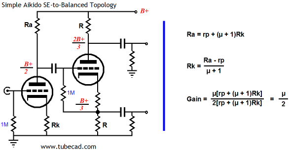
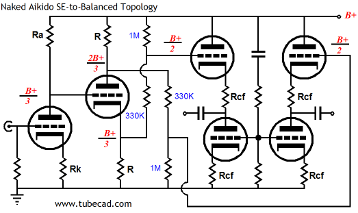
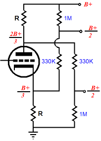
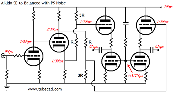
Stripped to its bare essentials, the circuit is shown above without the usual (and absolutely necessary) grid-stopper resistors or protective diode. Yes, it looks complicated, but it isn’t really. If you can work out the cube roots of six-digit numbers in your head, you will have no problem figuring this circuit out (just kidding; I wanted to see if you were paying attention). Let’s begin with the first half of the circuit, which looks similar to the preceding circuit, as they both hold a grounded-cathode amplifier and a split-load phase splitter. The grounded-cathode amplifier provides all the gain and it divides the B+ DC and AC voltages down to a third. (Once again, the cathode resistor cannot be capacitor bypassed, as it would spoil the noise-reduction technique.) The split-load phase splitter then does a great job of splitting the phase and it presents two different PSRR figures. The plate output leaks 2/3 of power supply noise at its output, while the capacitor output leaks only 1/3 of the noise. This is just what we want. Okay, so how do we make sure that the plate sees exactly one third of the B+ voltage? The following formulas spell out the required resistor ratios for the input stage.
There are two two-resistor voltage dividers following the split-load phase splitter; the next step is to examine what they accomplish. Note how the 330k resistors are roughly 1/3 the value of the 1M resistors, which ensures that each attenuator will pass 75% of the signal fed to its input. If the 330k resistor is a third of 1M, why isn’t the attenuation 66%? The formula for the amount of attenuation realized by a voltage divider is R2/(R1 + R2), where R1 sits atop R2. in this example, R2 equals 1M; thus, 1M/(330k + 1M) roughly equals 0.75. (Ideally, a resistor closer to 333.333k resistor should be used.) You might be thinking that I have made a mistake here, as one 1M resistor sits atop a 330k resistor while the other sits below a 330k resistor. There is no mistake here; the voltage divider on the left terminates into the B+, which should be a very low-impedance connection; the rightmost attenuator terminates into ground, which should also be a very low-impedance connection. Both attenuators achieve the same result: a halving of the B+ voltage and the B+ noise at their outputs.
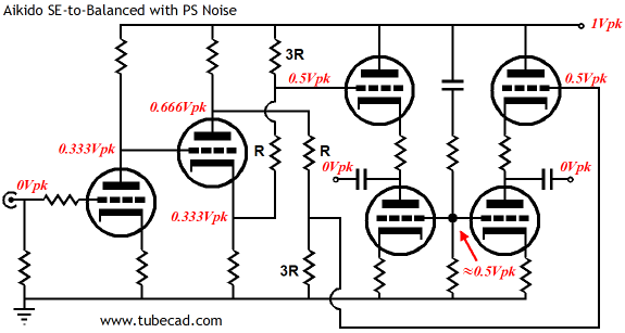
It might help to see what those voltage ratios would look like.
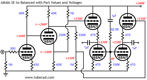
In the schematic above, we see a 300V B+ voltage stepping its way down to ground through our circuit. Now, lets see the same schematic but with an emphasis on the power-supply noise.
In the above schematic, "Nps" stands for power-supply noise. Okay, okay, I know that many just don't do fractions, so for their benefit the following schematic shows the noise as simple peak voltages.
One key point stands out: the DC and AC relationships do not match. In other words, at the output stage, the two Aikido cathode followers split the B+ voltage at their connections to their coupling capacitors, but the AC noise is nulled out of existence. Conversely, the two-resistor voltage divider that sits between these two cathode follower stages, sees none of the B+ voltage, but it doses halve the B+ AC noise.
Conclusion
Next Time
//JRB
|
Now accepting Support the Tube CAD Journal & get an extremely powerful push-pull tube-amplifier simulator for TCJ Push-Pull Calculator
TCJ PPC Version 2 Improvements Rebuilt simulation engine *User definable
Download or CD ROM For more information, please visit our Web site : To purchase, please visit our Yahoo Store:
|
|||||||||||||||||||||||||||||||||||||||||||||||||||||||||||||||||||||||||||||||||||||||||||||||||||||||||||||||||||||||||||||||||||||||||||||||||||||||||||||||||||||||||||||||||||||||||||||||||||||||||||||||||||||||||||||||||||||||||||||||||||||||||||||||||||||||||||||||||||||||


| www.tubecad.com Copyright © 1999-2008 GlassWare All Rights Reserved |