| John Broskie's Guide to Tube Circuit Analysis & Design |
27 December 2007 Two More OCRed Classic Articles
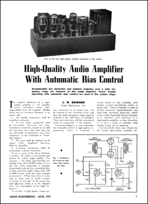
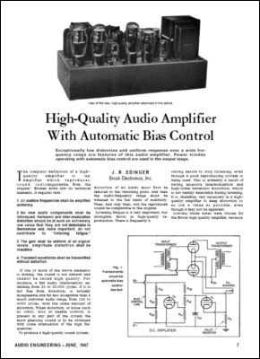
The above images show that the re-created page on the right is not identical to the original scan on the left, but being identical isn’t strictly the point. Much like our pursuit of re-creating acoustic events in our homes, the re-creation need only persuade the audience that it is real, not match in every detail the actual acoustic event. With high-quality audio reproduction, the more believable the better. To my ears, no matter how otherwise besmirched the signal might be, tube gear always contributes to a more believable musical presentation. (Well, that is about as far as I am willing to subscribe to the proposition that tubes make nice distortion, as I still adamantly proclaim that I love tubes precisely because of their low-distortion. Or as Dan Rather might say, It is better to be true but fake than to be false but authentic.) I have to step carefully here, lest I trip and fall into epistemological quicksand. Switching metaphors, Elvis may be alive in our hearts, but he is certainly dead on our LPs and CDs. If we can resurrect him in our ears, however, he can live again. Unfortunately, our high-tech necromancy often creates acoustic Frankensteins, whose scars and sloppy stitching are all too obvious. So much can (and usually does) go wrong that it is amazing that we bother to listen to any recorded music. Well, at least that is my consideration when I listen to the sound from stereos on display in big-box electronic stores. I can easily see many buying such sleek solid-state systems; I just cannot imagine anyone actually spending hours listening to them. Imagine never having heard a good vacuum-tube-filled amplifier, which cannot be that difficult as most of humanity has never heard any vacuum-tube-filled amplifier, as the worldwide median age is under 28 years old (if I remember correctly).
Ah, in days of old, when tubes glowed bold (Transistors weren't invented)… Indeed, I happen also to like the 1950s look in magazines, as it seems much more self-assured and calm. In sharp contrast, the Positive Feedback and Wired issues from the 1990s gave me a headache. In case you forget what they looked like, imagine having a new computer with 800 typefaces on it and the assumed obligation to use all of them at once, then add conflicting colors or too extreme a contrast between blurry heavy black text and white paper. Sonically, I’d say that we are in the 1990s of sonic reproduction, which implies that in ten years, all of us will be enjoying an easier-on-the-ears audio reproduction across spectrum of sound reproducing electronics, from singing greeting cards to iPods to TVs to home stereos. Today, it’s amazing enough that a greeting card can sing at all; in ten years, it will be amazing that it can sing so well. Just call me pessimistically optimistic. Mercy, that was a long introduction. The two new OCRed Audio Engineering articles are just a mouse button click away. The first is “The Sad Tale of a Half-Watt Resistor,” which is short and sweet. After reading it, see if you don’t recall the scene from the Woody Allen Sci-Fi movie, Sleeper, where after tasting the food of the future, Woody proclaims, “This stuff tastes awful. I could have made a fortune selling it in my health food store.” For the author who wrote,
How unlikely would be today’s audio scene, wherein a resistor that could—all by itself—add 4% of harmonic distortion would sell for at least at least $20, not the mere 10 cents he paid for it back in the 19950s. Just call me cheerfully cantankerous. The second article is “Effects of the Cathode Capacitor on P-P Output Stage.” I thought that this article would be worth reading in light of the following topic—namely, push-pull output stages with sliding idle current. But before leaving the topic of interesting PDFs, I have a pair of contemporary PDFs to recommend. The first is by fellow tube-lover Joe Curcio, who works for National Semiconductor. It's titled "Keeping Up With the Expanding Demands of High-Performance Audio." In it you will find many interesting circuits and the last paragraph even mentions vacuum tubes! The second PDF is shorter, but still makes some interesting points about the tradeoffs in capacitor design. "Low ESR Capacitors: Fact or Fiction?" by Mark Gebbia, of Illinois Capacitor, Inc.
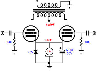
Push-Pull Output Stages and Sliding Idle Current Long ago, I read a great little book, The Tacit Dimension by Michael Polanyi, wherein Polanyi describes how a good bit of scientific knowledge and practice is never mentioned, but nonetheless essential. Analog electronics also holds its tacit truths and essential practices, which we all pick up as we do work in analog electronics. Well, I have several actual circuit-building habits that I seldom, if ever, mention, but that I always practice. One is to always scrape away oxidation from component leads before soldering. No big deal, right? I am not so sure, as I have experienced the odd result of having otherwise identical circuits sound different. A friend and I build the exact same circuit with the exact same PCB and parts from the exact same production lot, and my unit sounds better than his. My only guess is that clean parts sound cleaner than dirty parts. Of course, this isn’t a big deal with freshly made parts, but when using 40-yearold NOS parts, it’s essential. (Even as little as one year is enough to accrue some dull-gray oxidation on seemingly new parts.) Another practice of mine is to always place a 10-ohm-based RC filter in series with the input of my high-voltage regulators. I do this so out of habit that I don’t even add the RC network to my own schematics. Another no big deal, right? I would have agreed, just one year ago; but I ran into an interesting development when modeling a tried and trusted circuit in SPICE a few months ago. The circuit was a solid-state high-voltage regulator that I had built many times, with many different components and never with any problems. In the world of SPICE, however, the regulator blew up. My first thought was that the ideal parts of SPICE were at fault, that if I add real-life parasitics, such as ESR and ESL, everything would work again. It didn’t. Usually, it’s the opposite, a circuit works in SPICE, but not in reality, because of the non-ideal parts we use in reality. Well, I added my no-big-deal RC filter—How big a deal can a 10-ohm resistor and a 0.1µF shunting capacitor be after all?—and the regulator worked in SPICE as well as it worked in reality! And still yet another practice of mine is to always place a zener in parallel with a cathode-bias resistor in tube output stages. I do this for two reasons: I do not want the bypass capacitor to ever see an over-voltage and I want the limit the climb in cathode-bias voltage during loud passages, so that the output stage never moves too far off its correct bias point. An added benefit is that the zener adds a hard stop to the somewhat spongy and soft cathode resistor and bypass capacitor, just when the amplifier most needs to work against something solid. Besides, adding the zener is easy and cheap. Just specify a zener with a breakdown-voltage above the nominal cathode voltage. For example, if the cathode resistor sees a voltage drop of 15V at idle, then use an 18V to 22V 5W zener. By the way, I wrote quite a bit about the topic of automatic bias circuits and tube output stages a few years ago, so if you are new to the Tube CAD Journal, reading blog number 43 is a good refresher on the topic of using a zener clamp on a cathode-biased output stage.
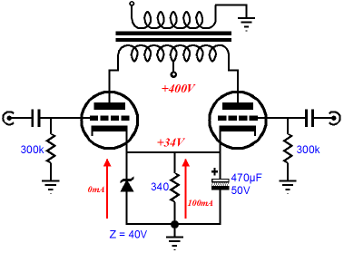
The above schematic shows a push-pull output stage with cathode bias and the zener clamp. At idle, the zener is effectively not in the circuit, as it conducts so little. But once its breaking voltage is reached, it conducts admirably, effectively shunting the cathode resistor and bypass capacitor. Now this same set of three components, cathode resistor, bypass capacitor, and zener diode, can be used on a single output tube, which will improve the idle-current matching between output tubes. (It’s a fun mental problem to work out why that would be so.) Now, a zener isn’t the only component that can be used to limit the voltage climb at the cathode. For example, a power transistor and two resistors can be used to make a pseudo zener.
In the above schematic, we see the single cathode resistor replaced by two in series. At idle, the voltage presented to the power transistor’s base is only 0.6V, which is not enough to turn on the transistor, so the transistor is effectively out of the circuit. But under the bigger current swings that loud music provokes, the base will see its turn-on voltage, usually 0.7V, and then it will conduct and strive to maintain a constant 40V at the cathode. This is a simple DC feedback loop at work. If the cathode voltage exceeds 40V, the transistor increases its conduction, pulling the cathode voltage down back to 40V. If the cathode voltage drops below 40V, the transistor ceases its conduction, allowing the cathode to fall back to its nominal 34V. In AC terms, the bypass capacitor passes much of the variation in current flow into the power tubes; thus, using high-quality capacitor in this position is essential, but using the bypass capacitor is not. We can bypass the bypass capacitor and leave it out of the circuit altogether. Or, we can bypass only one of the two cathode resistors. So, why use a transistor and an extra cathode resistor? The advantage power transistors hold is that they are cheap and easily heatsinked, which can allow for some intense heat dissipation. An added advantage is that the transistor-based voltage reference can make use of a potentiometer, which would allow adjusting the break voltage; very cool indeed. The downside to the transistor is that it is not likely to be as accurate as a voltage reference as the zener would be (although a power transistor and a low-voltage zener would probably be much more accurate a voltage reference) and it will creep out many tube fanciers to no end to see a TO-3 power transistor sitting in a tube power amplifier. Now, let see what someone else has done with transistor-based voltage references, thanks to Neal, a kind TCJer who sent me the information. In the following schematic, we see each output tube getting its own special cathode-bias circuit.
This schematic is from the Turner Audio website and I highly recommend that you read the long and detailed explanation of the circuit at the website. One problem I see with any cathode resistor setup is that the resistor is not a constant-current source, as it conducts linearly in relation to the voltage drop across its leads. This means that the resistor will fight the voltage climb at the cathode, as the amplifier is pressed into service beyond its class-A boundary. On the other hand, a true constant-current source would at least apply a consistent drag against the bypass capacitor’s climbing voltage.
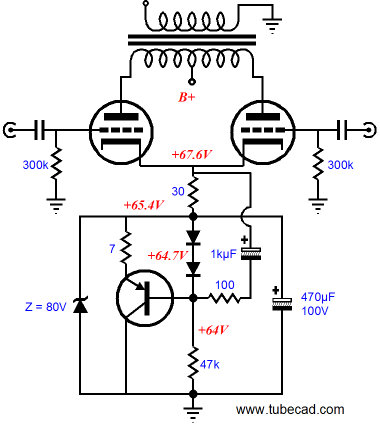
In the above circuit, we see the cathode resistor replaced by a constant-current source. This current source can be made up out of three-pin voltage regulators or many discrete components. (The famous LM317 is available in a high-voltage version.) But even the constant-current source will subtract from the available charging current that the bypass capacitor will see, slowing the voltage buildup. The circuit below makes use of a transistor-based constant-current source with a twist.
The twist is found in the 1kµF capacitor. This capacitor dynamically reduces the constant-current source’s nominally specified current. How? When the 30-ohm cathode resistor experiences increased current conduction beyond the class-A ceiling, the 1kµF capacitor tugs up on the power transistor’s base, thereby reducing the current conduction through the transistor, which will allow the cathode voltage to climb more rapidly. What happens if the capacitor pushes down on the base? Nothing much, as the two diodes in series effectively limit the base’s negative travel. (By the way, the voltages shown are no longer related to the previous schematics, as I took them from SPICE simulations I had run on the circuit, with 300B output tubes.)
Next Time
//JRB
|
Now accepting
High-quality, double-sided, extra thick, 2-oz traces, plated-through holes, dual sets of resistor pads and pads for two coupling capacitors. Stereo and mono, octal and 9-pin printed circuit boards available.  Aikido PCBs for as little as $24 http://glass-ware.stores.yahoo.net/
Now accepting Support the Tube CAD Journal & get an extremely powerful push-pull tube-amplifier simulator for TCJ Push-Pull Calculator
TCJ PPC Version 2 Improvements Rebuilt simulation engine *User definable
Download or CD ROM For more information, please visit our Web site : To purchase, please visit our Yahoo Store:
|
|||


| www.tubecad.com Copyright © 1999-2007 GlassWare All Rights Reserved |