|

Still more phono preamp circuits. Why? If you have given up on LPs or if you are too young to remember them, then I can understand your bewilderment and I fear that nothing short of sitting you down and playing an LP is going to succeed in changing your perspective. Well, I just listened to a 47-year-old LP: Harry Belafonte’s My Lord What a Mornin’ on RCA. I am amazed by how good LPs can sound.

Yes, it is a black-label RCA, so we should expect good sound. But then we should expect that 47 years later that we should have so much better-sounding recording media that this half-century-old LP should sound embarrassingly bad by comparison. In 1960, surely that was the expectation—surely, the future would deliver something close to perfect sound forever. I can imagine someone in 1960 being disappointed that we do not drive flying cars today, but he would be impressed by many new cars, with their hybrid engines, DVD players, and GPS navigational systems. On the other hand, I can easily imaging him cringing from the sound coming off most modern CDs. What went wrong?
I have my own convoluted theory.
The acoustic-suspension loudspeaker is to blame. Before its advent, loudspeakers were either horn-loaded or bass-reflex or infinite baffle in design—no matter what the design, however, they were efficient and big. The acoustic-suspension loudspeaker is neither. In perfect compliance with the laws of nature, the acoustic-suspension traded efficiency for extended low-frequency response (and small size). At the time, it seemed to be a good deal, as tube-based amplifier were getting more powerful, thanks to the 6550/KT88 and the EL34 pentodes. And solid-state power amplifiers were becoming common and cheap. So, instead of housing huge loudspeakers and flea-power amplifiers, most were happy listen to small loudspeakers and live with high-power amplifiers. So what was intrinsically wrong with this bargain? The acoustic-suspension loudspeakers sounded just dreadful.
Listen to an old, old acoustic-suspension loudspeaker, with modern audio gear; you will hear the slowest, most turgid and dead sounding loudspeaker possible. Listen to an old solid-state power amplifier, and you will hear the most brittle, screechy, harmonically desiccated amplifier possible. Truly dreadful. (And yet both received laudatory reviews at the time...remember Stereophile’s I’ve-just-wet-my-pants glowing review of the first CD player?) Digging into why those early solid-state power amplifiers sounded so appalling bad would take twenty long blog entries; explaining what went wrong with those early acoustic-suspension loudspeakers takes two words: heat and stuffing. Of course extra detail is always welcome. An inefficient loudspeaker must convert the great surplus of input power into heat, as so little is transformed into sound. Now the problem with heat is that it is slow to accumulate and slow to dissipate. This is not good for a voice coil. The problem with stuffing, by which I mean excessive stuffing, is that it is like adding dielectric absorption to a coupling capacitor, as the air trapped in an acoustic-suspension loudspeaker is like a capacitor and the stuffing is like placing a resistance in series with the capacitance internally, which slows the charging and discharging of the capacitor.
How do acoustic-suspension loudspeakers get overstuffed? Much like small-breasted women getting triple-D implants and power amplifiers with Coke-can-sized reservoir capacitors: more must be better. If your loudspeaker is stuffed tight with fiberglass or dacron, try this simple experiment: remove all but a small wisp of filling and listen. Yes the frequency response be be a bit lumpy, but at least the sound will not sound lifeless. (In the old days, the procedure was to place 1 inch of fiberglass on the top, one side, and the back of the enclosure—and that was it.)
Well, it turned out to be a bad coincidence that a slow, turgid, dead-sounding speakers makes a good complement to a brittle, screechy, and dry-sounding amplifiers. In fact, the two sets of sonic vices almost cancelled perfectly; well, at least well enough that it has taken decades to undo the two wrong turns.
(It is quite telling that those who owned electrostatic loudspeakers NEVER gave up on tube amplifiers, as their high-resolution loudspeakers quickly revealed the early solid-state amplifier’s painfully gritty sonic texture.)
By 1980, the not-insubstantial achievement of making LPs sound bad had become routine. All the tube-based equipment had been removed from the recording studios, replaced by cheap, horrid-sound IC-based gear. The old family recipe of making thick, flat records had been lost and forgotten. At the CD’s birth, the CD met a weakened and battered opponent; thus, it isn’t at all surprising that the CD effortlessly won the format war. The only complaint I remember hearing from non-audiophiles at the time was, “You can’t record on it; so, what good is it?” (I knew many music lovers who had forsaken the LP for the audio cassette and the ability to record was all important.)
Now, what if—the historian’s most intoxicating phrase—what if the acoustic-suspension loudspeaker hadn’t arrived on the audio scene when it did? What if high-efficiency, high-resolution loudspeakers had remained dominant? Would solid-state power amplifiers and CDs have stood a chance against more-highly-evolved tube amplifiers and LPs and phono cartridges and turntables and loudspeaker?
No doubt that solid-state devices would still fill our TVs, cell phones, and computers, but, just perhaps, the audio branch of the tube family would have survived and flourished, while the radio and TV tube branches withered and perished. Just ten more years of research and development on audio tubes would certainly yielded great results. Computers could have helped in modeling the tube’s complex internal geometry. The Japanese improvements in picture tube cathode technology could have been applied to 12AX7s. And laser-cut grids might have become standard issue. Well, I can dream can’t I?
Blog number 75 demonstrated how a balanced-output DAC could differentially drive a single-ended grounded-cathode amplifier. (Turning balanced into unbalanced is easier than you might presume.) Of course, DACs are not the only balanced-output signal sources, as many new pieces of stereo gear sport XLR output jacks. And any signal generating device, such as phono cartridge or microphone, can be configured to yield a balanced output, as long as no lead is directly grounded. Well, my last entry ended with a teaser: a schematic of a balanced connection from a phono cartridge to the front end of an OpAmp-based phono pre-preamp that differentially drove a single-ended tube Aikido gain stage.
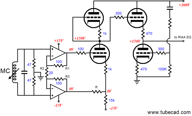
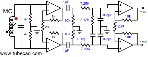
The phono cartridge’s connection to ground is via the two 47-ohm resistors, whose nexus defines the null in the balanced output from the phono cartridge. The two OpAmps amplify their input signals by 11 (+20.8dB), a the gain per OpAmp equals 1 + 2R1/R2, where R1 = R3.
One important detail to remember is that we have split the output signal from the phono cartridge, so each OpAmp only sees half the signal that one OpAmp would see in a conventional unbalanced configuration; since the OpAmps outputs are balanced, however, the total differential gain is twice as big; thus, no gain was lost in the amplification of the phono cartridge’s output signal.
The top OpAmp drives the triode’s grid through a grid-stopper resistor and the bottom OpAmp drives the triode’s cathode through resistor R and through a 1k cathode resistor. Why the extra resistor R? The gain from the cathode is greater than the gain from the grid, (mu + 1)/mu more in fact. The added resistor equalizes the gain from both triode inputs, so that the full possible CMRR from the triode can be realized. (Imagine that both grid and cathode receive the same signal, in the same phase and amplitude; now imagine what the signal at the plate would look like if cathode’s non-inverting amplification were added to the grid’s equal inverting amplification; nothing, a null, in other words, should be the result.)
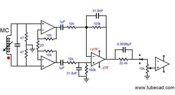
The OpAmps, on the other hand, provide a fairly mediocre CMRR as configured, as a common-mode signal passes at unity gain to the OpAmps’ output. Thus if 1mV noise appears at both inputs, 1mV of noise will appear at both outputs. In other words, the CMRR equals the gain, as the voltage gain over the common noise voltage is how common-mode rejection is measured. It could be worse. For example, in the circuit below, we see a complete phono preamp, albeit an all-solid-state preamp, with the frontend wired in a traditional fashion.
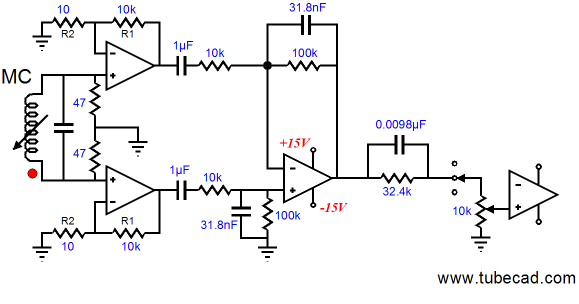
The gain per input OpAmp equals (R1 + R2)/R2. The CMRR is zilch, so a common-mode input signal of 1mV is amplified by both input OpAmps by 1001, in this example. The following stage, however, does deliver a CMRR as good as the resistors are matched.
(If this phono preamp does not seem to make any sense, just read blog number 118 to see how the inverse RIAA equalization is implemented.)
The 1µF inter-stage coupling capacitors save the differential second stage from seeing large DC offsets at its inputs and they ensure that the second stage’s output will be free of offset. Now, let’s see what this circuit would look like with the better configuration of the input stage.
With this arrangement, we get the same gain from the input stage and we pick up a healthy CMRR due to the high gain (+60dB). We still have to use the inter-stage coupling capacitors, but I do not see them as being great liabilities, as to extended a low-frequency bandwidth can be a huge pain when playing records. Few LPs are flat and all turntables create low-frequency rumble; it’s just the nature of mechanical things to grind and groan. (Even if your $100k turntable is perfect, the cutting lathe most certainly wasn’t.) The 1µF coupling capacitors imposed a -3dB transition frequency of 16Hz, which is about as low as I would be willing to go.
Since a phono preamp designed for use with a moving-magnet or high-output moving-coil phono cartridge will need much less gain (20db less, let’s say), we can probably get away with a single coupling capacitor, as the differential frontend achieves a gain of only 100 (+40dB).
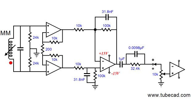
In the schematic above, we see the sole coupling capacitor placed at the second stage’s output. This—and the previous two—phono preamp makes use of the alternative RIAA equalization configuration, wherein the signal sees a 50Hz low-pass filter then a shelving network that attenuates frequencies below 2122Hz and then flattens at 500Hz (see blog 118 for more details).
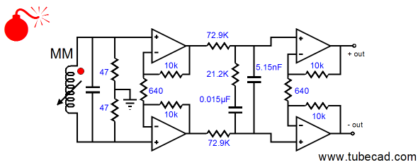
Some run their entire systems in balanced mode. Making a balanced phono preamp is not difficult, although a few traps await the unsuspecting. For example, in the circuit below, the pass RIAA equalization network works both signal phases against each other, which means that any departure from perfect balance will trip up the equalization.
On the other hand, adding just one more capacitor and referencing the 2122Hz pole to ground will preserve a much more accurate final equalization, in spite of slight imbalances. (This is something will not show in a SPICE simulation, unless you go looking for it, as SPICE parts come perfectly matched.)
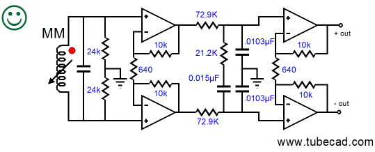
An MC version requires more gain and, as a result, two coupling capacitors to keep the DC offset at a safe level.
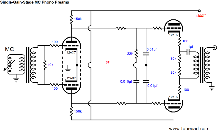
We finally arrive. The following idea may be crazy and good or crazy and not good. Actual soldering-fumes-our-noses experimentation is required. The circuit below may look fairly normal, but it isn’t. Just as sitting before a performance by the First Symphonic Ensemble (Pervyi Simfonicheskii Ansambl) might have seemed perfectly normal, but it wasn’t.
Ok, enough suspense. Look at the phono cartridge and its loading resistor and shunting capacitor and the two grid-stopper resistors—Where is the connection to ground? There isn’t any; the grids are left floating. What!? You cannot do that; without a negative bias voltage, the input triodes will catch on fire. Actually, they won’t. If nothing else, the plate resistors limit the maximum cathode current to B+/Ra, which might be only 2 or 3mA. And the grids will not climb to several hundreds of volts; in fact, the grids will end up biased to something like -1V. What?
If you could climb inside a tube’s envelope with a voltmeter in hand, you could measure the voltage gradient from cathode to plate. Here’s what you would find: the cathode emits a cloud of electrons, most of which travel up to the plate, some, however, fall back towards the cathode, which creates a negative zone within a gradient that starts at 0V then moves slightly negative (say -1V) then linearly climbs positively to the plate voltage. The cartridge’s coil attaches only to the grids, which sit in the negative portion of the voltage gradient, so the coil becomes charged negatively as well. Had the phono cartridge been grounded through a two-resistor voltage divider to ground for example, then the grid and cathode would share the same DC potential and the idle current could climb dangerously high. Finding the idle current with out a ground reference takes some actual experimentation: attach a B+ voltage (150V, for example) to the plate and ground the cathode, but leave the grid floating. Then measure the idle current, it will not be nearly as high as you would expect. (Once again, if the grid is grounded, however, the current will shoot up to B+/rp.)
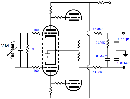
The following preamp builds on the previous design. Two step-up transformers provide a ton of gain and the 12AX7 provides x70 worth of gain, so the total gain would be +60dB at least. Note that there are no cathode resistors on the 12AX7 and that the input transformer is floating, with no ground connection! (If less gain is needed, the input transformer can be removed and the cartridge coil would be left floating. Assuming a gain of about x70 (+37dB) from the 12AX7, the output transformer’s step-up ratio need only be 1:14 to get to a final gain of +40dB.) The output transformer can be a high-quality, nickel-core, as no DC current flows through its primary. The CMMR should be excellent, as that is what transformers do best (well, at least at lower frequencies, as the inter-winding capacitance can degrade the high-frequency isolation between primary and secondary).
Because everything is balanced between the input and output transformers, all common-mode signals, such as power-supply noise is dropped from the output. So, there it is: a simple, four-tube, MC phono preamp that neither requires a lot of parts nor a great power supply, not bad..but then I am biased, or is it that I am biased for unbiased preamps?
//JRB
|


