| John Broskie's Guide to Tube Circuit Analysis & Design |
|
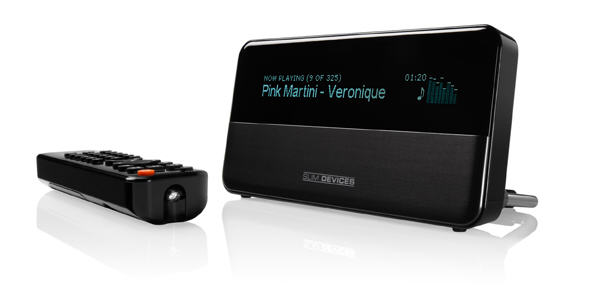
08 March 2007 More on Tube Tidbits Make magazine delivers once again. No, not a new tube amplifier, but a tutorial on soldering. In fact, if you dig through the website, you will find a 19 minute video that shows how to solder. Maybe you have wondered why I am using two schematic layouts, one with a gray background and one without a border and a white background. The answer is that I have gotten many e-mails complaining of the excessive ink (and toner) that printing my blog entries requires. This webzine/blog gets printed; I know this because every time I make a non-printable error on the site, I hear about the next day. In fact, while at 2005 CES, I met a reader who told me that his wife has an interesting expression, “Where are we taking Mr. Broskie today?” You see he has printed every page of this website and he drags his thick binder with him everywhere he goes. So in order to conserve ink, I have reverted to white backgrounds, but thicker lines. Well, when ever I haven’t already drawn the schematic, that is. (I have to conserve my energy as well.) By the way, I recently picked up a Slim Devices Squeezebox and I love it. In case you have just come out of a three-year coma and you have never heard of a Squeezebox, here is a quick description. It is a small box that connects to a stereo system, allowing you to stream digitally encoded music from either your computer or from a DSL line. The $250 version requires a cable, but the $299 version picks up Wi-Fi.
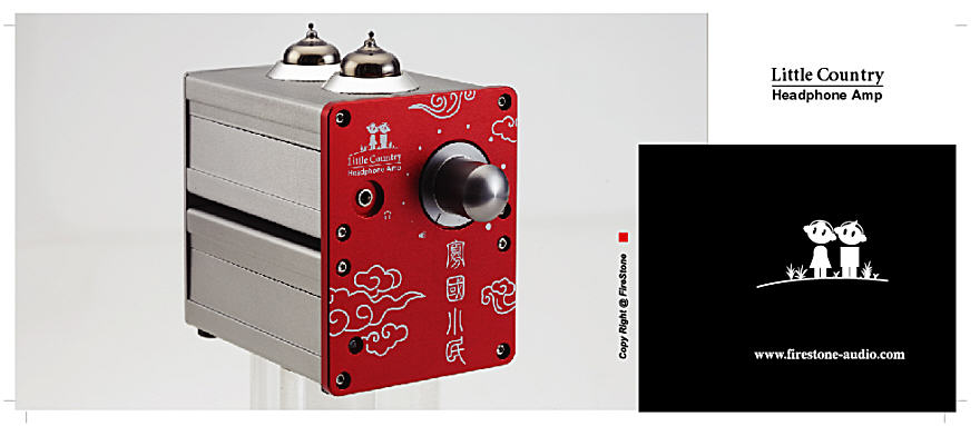
With my fast DSL connection, I can pick internet radio streams from around the world, while my computer is turned off! My wife and I fight for the remote, as we have differing tastes in radio stations; she prefers setting the box to Paris radio stations (she did live there a year, while she attended university). I prefer the BBC and will check out other European radio stations soon. If you thought that internet radio was a waste of time, you are right... if you are talking about hearing it on your computer’s pathetic loudspeakers. On a better sound system, the results are quite listenable. It turns out that I have 485 CDs ripped in lossless WMA files on my hard drive, which I can now access from my living room (when the computer is on and the SlimServer is running). I love it, although I have to admit that my CD player, playing the same CD, sounds much better. Still, it is wonderful to select random play and twenty day of non-stop, non-repeating music. By the way, because of limitations of the DAC and OpAmps within the Squeezebox, I am thinking of adding an external DAC. (In fact, I am thinking of offering a DAC PCB. Remember how well the Aikido-based DAC did at the ETF’s DAC shootout? I do) Here is an interesting tidbit: you do not even have to have a stereo system to enjoy a Squeezebox, as it holds a headphone jack. However, much better listening is possible with a Squeezebox and a tube-based headphone amplifier. Speaking of which, my friend David Lin, of Firestone Audio, has created a gem of a hybrid headphone amplifier, the “Little Country” headphone amplifier:
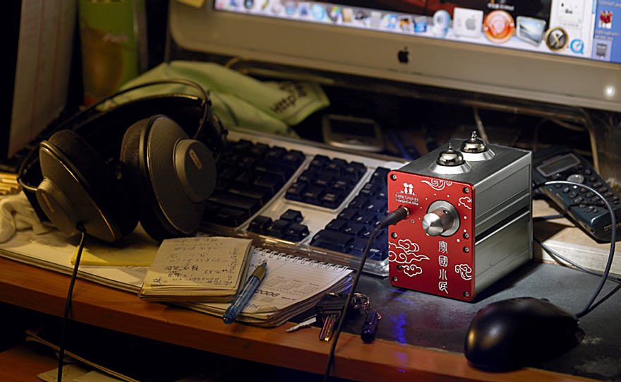
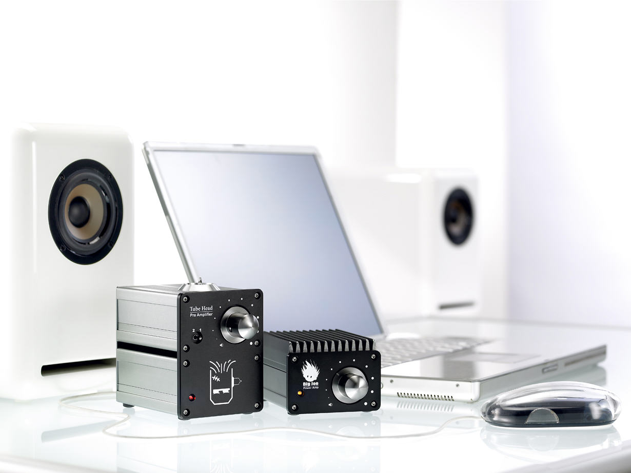
Small and beautiful, all his audio products remind me of humming birds. I own a “Tube Head” preamp and a “Big Joe” power amplifier; not just great sound, but so cute that you have to love them. Now with a Squeezebox, a Little Country headphone amplifier and a pair of good headphones-- life can be quite delightful. (Don't get the wrong idea: this headphone amplifier is not a toy; it holds an ingenious hybrid circuit that uses a 12AX7 and a 12AU7 and class-A, single-ended, hybrid output stage.)
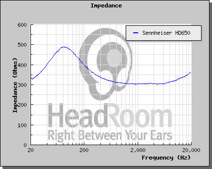
Current-output amplifiers Which headphones would make the best fit with a tube-based current-output headphone amplifier? Everyone’s first impulse is to go with the Sennheiser 300-ohm headphones, such as the HD580s, HD600s, and HD650s. Well, this might be the wrong choice. I have found that my HD650’s require a low output impedance amplifier to produce clear bass. (I remember reading somewhere that Sennheiser recommended low-impedance amplifiers with all their headphones, contrary to the industry standard of 40 to 100-ohms output impedance.) The graphs below were taken from HeadRoom’s website. Note the impedance spike at around 80Hz with both headphones.
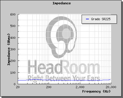
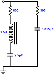
Now compare the Grado SR225’s impedance curve. Yes, the graph artificially flattens the impedance plot because of the high Y-axis scaling. Nonetheless, to my eye, the Grado seems to present a flatter impedance curve. One workaround (for both headphones) would be to place a Zorbel network in parallel with the headphones, which would flatten the high-frequency impedance climb. Fixing the low-frequency impedance spike would require a three-element compensation network. Combined, the circuit would look something like this for the HD650s:
This network in parallel with the headphone driver results in a flatter impedance curve.
XPP amplifier
In performing SPICE simulations on the XPP amplifier, I was struck by how low the distortion was into low-impedance loads. The optimum voltage swing was greatly reduced by the low impedance load, but the waveform was still pristine. In contrast, the typical tube-based voltage amplifier distorts egregiously with low impedance loads.
First of all, note the 1-ohm load! The translation of dB into percentage of distortion is this: -40dB equals 1%; -60dB, 0.1%;-80dB, 0.01%. Of course, the XPP amplifier can only deliver a tenth-of-a-volt swing into the 1-ohm load, but that tiny voltage swing is cleanly rendered. (In order to test the XPP amplifier, I hoped that I would be able to hack one of my Aikido PCBs to accept the XPP circuit instead. I couldn’t; well, at least not without cutting PCB traces.)
Zen-like current-output power amplifiers
Above, we see the basic idea behind the Zen amplifier. The input signal works against the bottom MOSFET’s transconductance to modulate the current flowing through the bottom MOSFET, which is then delivered into the load impedance. A feedback loop extends from the amplifier’s output to its input and fixes the gain and lowers both distortion and output impedance, while extending bandwidth.
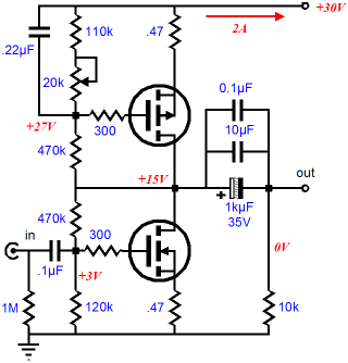
Now, if we lose the feedback loop, as we have done in the schematic above, the amplifier defaults to a current-output mode, as the MOSFET’s drain offers little resistance to AC signals. Yes, the output impedance will be astronomically high, but then that is what we desired from a current-output amplifier. The higher distortion was not, however, on our list of objectives. Thus, some form of feedback must be added, but without returning the amplifier to a voltage-output mode. The easy solution is to add a little unbypassed source resistance (as shown below), which will introduce some degenerative current feedback (and offer some added amplifier safety, as the added resistance will limit the maximum current conduction that the bottom MOSFET can undergo). In other words, any deviation the MOSFET’s source takes from the gate’s course results in the MOSFET bucking that deviation by increasing and decreasing its conduction to counter the wayward movement.
Since we gained increased linearity, what did we give up? Remember, free electrical-engineering lunches only occur in the ads in glossy audio magazines. We paid for the linearity with decreased current gain, as a MOSFET's effective gm with an unbypassed source resistor is:
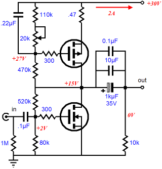
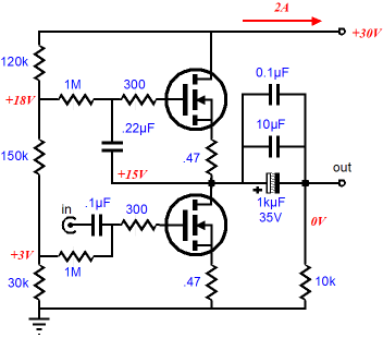
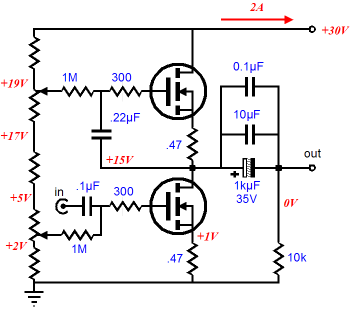
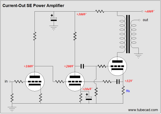
The above schematics show a variation that allows the idle current and the output stage voltage centering to be adjusted separately. How can the Zen-like, MOSFET-based circuit be translated to vacuum-state technology? (I know that I am getting the order wrong here; I should have shown the tube-based circuits first, then the solid-state versions. Am I not the master of my fate, the captain of my soul?) Well, since P-channel MOSFETs find no equivalent in the tube world, the first topology cannot be translated; the second, with its exclusive use of N-channel MOSFETs is a breeze.
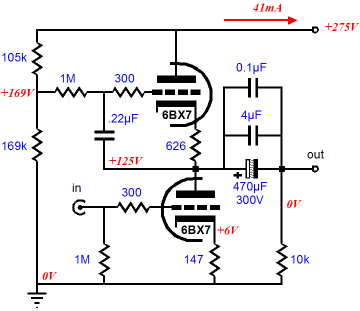
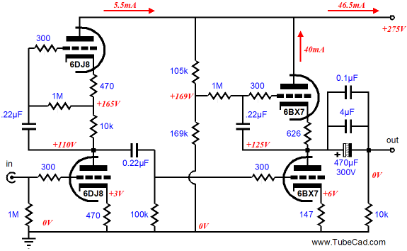
In the schematic above, we see a simple one-stage current-output amplifier. Triodes are used, but pentodes could be used almost as easily; in fact, a blend of both might prove best. The bottom triode varies its conduction based on the signal voltage presented to its grid, while the top triode works as a constant-current source of sorts, as its effective impedance equals: Since we have gone this far with our calculations, let’s finish this current-output headphone amplifier. Let’s pick a target peak output current of 31mA, which I believe is the iPod’s maximum into a 32-ohm load. Now, 31mA divided by a transconductance of 1.24mA/V equals 25V of required peak input voltage. Thus, if we expect 1V of input signal to drive this amplifier to full output, we will have to abandon the single-stage concept and realize that an input transformer with a winding ratio of 25 or an input stage with a gain of 25 will be needed. Good signal transformers are expensive and hard to find, so let’s look at the second choice. Of course, the Aikido amplifier would be a sterling choice, but as we are using a constant-current source (of sorts) for the output stage, it would be fitting to use one for the input stage as well.
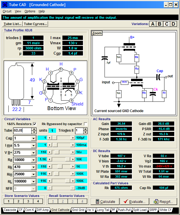
The input triode, a 6DJ8, is loaded by a constant-current source, whose effective impedance equals 360k. The gain is close to 25, coming in at 26:
One quick variation
The idea behind this circuit is that first stage DC couples to the second stage and that a feedback extends from the second stage to the output stage. I didn't specify values for the two feedback resistors, as I feared having them set in stone. Nonetheless, reasonable values might be 47k and 100k. As always, much experimenting is needed; as always, most just want a proven recipe or a map with the hidden treasure clearly marked. John Atwood has reminded me that I must mention that output transformers produce the least distortion with low-impedance output devices, not high-impedance devices. Here is a link to more information.
Next time //JRB
|
|


| www.tubecad.com Copyright © 1999-2007 GlassWare All Rights Reserved |