| John Broskie's Guide to Tube Circuit Analysis & Design |
27 September 2006
Aikido headphone amplifier recipe Here’s some autobiography: My nickname was “John the Electron” and I grew up in Silicon Valley, where the air was redolent of soldering rosin fumes and electrical engineers were as common as lawyers in Los Angeles. I am half as old as the triode and as old as the hard drive: in other words, 50 years old. In 1970, I was 14 and impatient to move beyond DC circuits into the world of AC electronics. And while I have always owned a tube amplifier, my interest in audio electronics began with solid-state circuits. Why? Back then, every supermarket’s magazine rack held at least two electronics magazines and several hi-fi magazines. In these magazines, tubes were universally scorned and solid-state beckoned and tantalized with its promise of a miniaturized, cool, and efficient future. So although I learned tube theory, it was only as an obligation, as my real interest was in the exploding developments in solid-state circuits, which had broken free of coupling capacitors, moving towards completely symmetric constructions and DC coupling throughout. Because most of my electronically minded friends were entirely swayed by the simplicity of OpAmp-based circuits, they could not understand my fascination with the topologies within the IC package. Like Nelson Pass, I loved studying IC user guides from National Semiconductor. For me, the timing was perfect. Like a teenager growing up during a gold rush, I reveled in the explosion of new circuit topologies and new electronic parts, such as the power MOSFET and IC. (Remember the gridister and the ring-emitter transistor?) Expansion thrills; contraction dispirits. By 1980, I had designed and built at least three phono preamps and power amplifiers—all solid-state. My efforts well received by my audiophile friends, but one stubborn problem irked me. Why did tube gear always sound better than its supposedly superior solid-state replacement? How was it possible for the antique and clunky (and, indeed, chunky) tube to sound so much better? Such an outcome seemed as improbable as a WWI Fokker D7 biplane shooting down an F/A-18 Super Hornet. (The 1970’s produced the some of the worst-sounding solid-state audio gear; thus, it was easy for a moderately modified Dynaco ST-70 to walk all over the most expensive solid-state amplifiers, magnificently icky amplifiers. Yet these solid-state amplifiers received glowing reviews at the time.) Well, it was back to the old tube-electronic textbooks and magazine articles for me. By the late 1980’s, I spent thousands of hours in university technical libraries, searching, reading, deciphering old tube-knowledge treasures. About then I discovered the Tube or not tube book (and Audio Update magazine) from the folks at Audio Dimensions in San Diego; I drove down and bought my copy in person at their store. Later, I came across the distinguished Japanese audio-electronics magazine, MJ Stereo Technic. Remember the line from The Tempest: “Oh brave new world, that hath such people in it…” That’s how I felt as I gazed at original, ingenious, pioneering circuits, both solid-state and tube-based. Like one drunk with gold, I was intoxicated by the possibilities with that magazine. Few of my electronically-minded friends shared my tube interest and those that did held to the view that tube circuitry had come to a topological dead-end decades before. (Just the other day, a tube-loving, Aikido-owning friend asked me if there had been any original tube circuits in the last fifty years! For many, it seems impossible for there to be anything new under the sun.) The expansion during the 1980s was thrilling. Then came the 1990s. I, for one, was quickly dispirited. In spite of the tube’s miraculous rebirth and the Internet’s coming of age and the multiplying of those interested in tube electronics, the exploration of new tube-electronic possibilities diminished before my eyes. Each subsequent issue of Glass Audio proved more boring the previous one; tube gurus popped up everywhere, yet few had more than the grounded-cathode amplifier topology under their belt. It felt as if the Big Bang’s expansion had come to an end and everything was retreating to a single point in the universe. It was in this state, both mental and actual, that I began the Tube CAD Journal. I wanted to push out against the contraction. (Perhaps, only I perceived a withdrawal into a staid and settled past. Here is an analogy: For one year, I was a resident of San Francisco, the year 1980. No matter to whom I spoke, I always heard the same story: “This city used to be something special, but it no longer is.” No matter whether my fellow resident had moved there in the 30s, 40s, 50s, 60s, 70s, each told me how when they had arrived, the city was tenfold more interesting and exciting than it was today. In fact, even I say the same thing about my single year there, calling it San Francisco's last good year, as I lament the loss of distinct neighborhoods, jazz and blues venues, freeways through the city, and so much more… Maybe, during the 1990s, readers who were in their twenties felt that that decade held the purest, ceaseless tube-circuitry expansion.) The second reason I hate chiseling one specific circuit in marble is that I do not worship at the Altar of the Absolute Tube Circuit. I know better than to imagine that one circuit is perfect without specifying the conditions that must be satisfied to define perfection. In other words, it is impeccably foolish to speak of perfection without first answering the implied sub-question, “Perfect for what?” In the same way, we cannot decry a circuit as a bad without identifying at what it is bad. Nor do I believe that for any given circuit, there is only one sweet spot, whose part values and tube type and tube brand cannot be matched; as I know that there many sweet spots waiting to be discovered.
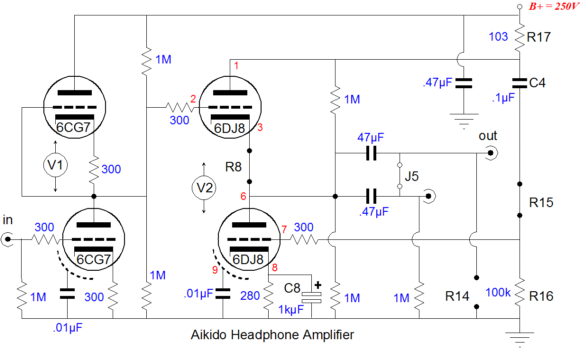
So it is with much mental arm twisting that I lay out one Absolute Tube Circuit. In the schematic below we see the authorized Tube CAD Journal Aikido version of a tube headphone amplifier.
The 6CG7 provides a gain of 10 (or +20dB) and little distortion. Indeed, the 6CG7 is a fabulous tube. It was created to be a 9-pin substitute for the octal 6SN7. In one important respect, it is better than the 6SN7. Unlike the 6SN7, the 6CG7 holds an internal shield. This flat, rectangular divider keeps the two triodes from interacting with each other. Remember the electrostatic fields around a triode do not stop at its physical structure. By placing a grounded shield in between, the interaction is diminished substantially. An added bonus falls our way in the additional stiffening that the shield brings to the rickety internal tube structure. The 6FQ7 suffers from its absence. The 6DJ8 / 6922 / 7308 / E88CC (and not 6ES8 or 6N1P) is well known and readily available. Its high transconductance ensures a low output impedance (about 50 ohms in this circuit). Furthermore, its low rp allows large current swings into low-impedance loads. And, like the 6CG7, it holds an internal shield. The 47µF coupling capacitor allows bandwidth down 12Hz into a 300-ohm load, such as the Sennheiser HD580, HD600, HD650 headphones. If 32-ohm headphones are used, then a 470µF coupling capacitor will be needed, which electrolytic capacitor, as a 470µF film capacitor would be wallet-wrenchingly huge. The 0.47µF coupling capacitor works as a bypass capacitor for its larger mate and it should be fairly small, as a 470µF film capacitor is huge. (I prefer higher-voltage capacitors, but a 250V capacitor is much smaller than a 630V capacitor.) If this Tube CAD Journal approved arrangement is not to your liking, then download the user guide, wherein you’ll find four other possible recipes.
Reiffin's SE cathode-follower power amplifier
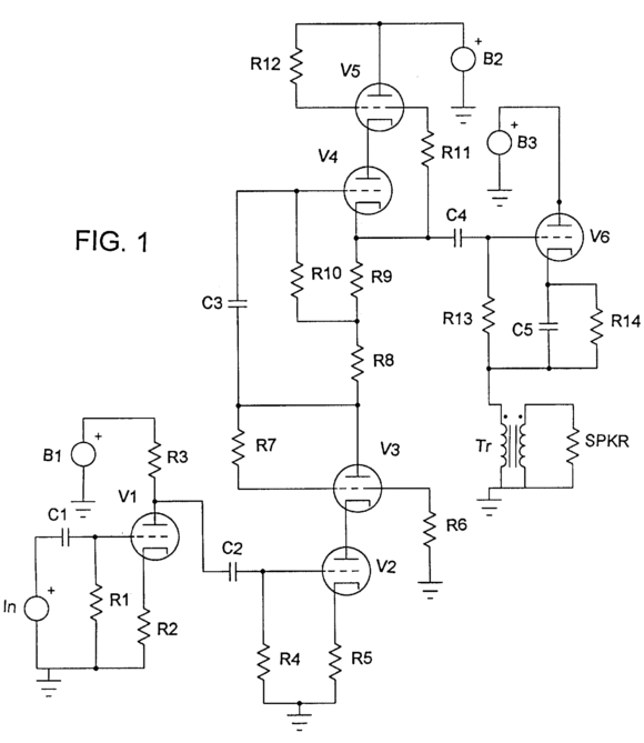
I feel that I should mention that Marty is a friend of mine, before we look into his invention, as he is something of a controversial figure in electronic world. Now on to his design, Reiffin has devised a (push-pull) driver stage to drive an SE, cathode-follower-based output stage.
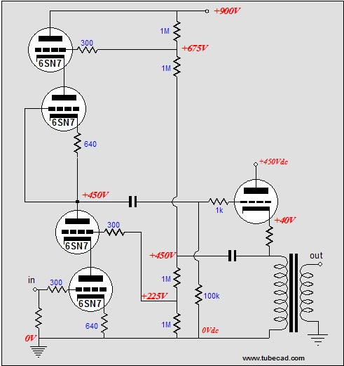
Mamma mia, that’s some spicy driver stage. "Spicy" in the sense of SPICE, the circuit-simulation software program. I can usually spot a SPICE-influenced design at twenty feet with one eye closed and this circuit looks quite spicy indeed. Still, how you come up with a circuit is not as important as how well it works. And how well does this circuit work at it achieving its goal of providing a large voltage swing? Since I do not have a regulated 900V power supply and because I am lazy, I modeled his driver stage in SPICE. Below are both the circuit and its SPICE-derived DC operating voltages.
I do not know which tubes or part values Marty recommends, so I choose a 6SN7 with about 200 volts across each triode and an idle current of 10mA. Everything looked right, so I moved to some transient testing, feeding the bottom triode an input signal of 50Vpk. Wow! This baby can swing voltage, +1,720V and -1,640V. Wonderful in every respect, apart from the impossibility of swinging an output voltage greater than the power supply B+ voltage, which was only 900V. What happened? The SPICE model is based on the mistaken, but universally held view that a triode is a variable current source; it’s not. A triode is a variable resistance, not a variable current source. A fully saturated inductor is a current source until it runs out of steam, just as a fully charged capacitor is a voltage source until it is completely discharged. In reality, unless a voltage source (such as battery or a charged capacitor or solar cells or a conventional power supply) is attached to a triode, no current flows. In SPICE, however, the triode models generate current even in the absence of any power supply. How’s that for an energy-saving device? Let me be clear here: the problem lies not with the SPICE engine, but with the faulty models used in SPICE. (Once again, my strong ambivalence to SPICE is highlighted. I love SPICE; I dislike SPICE; and I always begin to worry when someone else hands me some SPICE results. My motto is that SPICE gives the best results when you already know what the results should be.) If we cannot trust the results from SPICE in evaluating Marty’s driver stage, is the only recourse to build a 900V power supply? Well, no. We can still use SPICE by limiting the input signal to the peak value require to ensure that the bottommost triode sees a zero-voltage differential between its cathode and its grid, as beyond this limit the grid begins to conduct in earnest and draws current, which drags down the preceding input stage. The maximum peak input voltage I found to be 5.1V, based on my part choices. (Another tack would be to place a current meter in series with the driver stage read the input signal voltage when the peak current draw climbs to 18-19mA, as the driver stage will leave class-A operation beyond 20mA.) So after feeding an input signal of 5.1Vpk, what do we get? Not that much, only 176V of swing. Considering the 900V power supply, I would expect much more. And much more would be needed to drive most output tubes to full power. For example, a 300B working into a 3k primary with an idle current of 80mA would need to achieve 240V cathode-voltage swings, which would require that its grid see at least 240V plus the cathode-to-grid voltage at idle, say 60V, for a total of 300Vpk, 600Vpk-to-pk. Replacing the 300B with an EL34 or KT88 would help to reduce the drive voltage requirement, but 176V would still fall far too short.
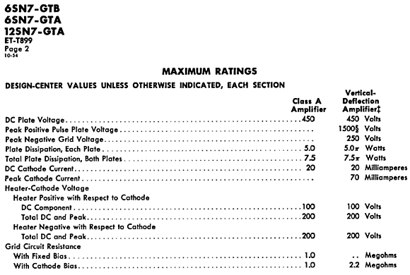
Now let’s look at some alternative topologies. The Aikido could be used, if a few key stipulations were observed. The first is that the top and bottom triodes would require horizontal packaging, not vertical. In other words, the bottom input triode and the bottom output stage triode must be located in one tube envelope and the same holds true for the topmost triodes. Why? The cathode-to-heater voltage is only 100V for the 6SN7 and referencing the heater power supply at the middle of the top and bottom cathode voltages would place it at 243Vdc, which would exceed this voltage limit for both triodes. On the other hand, if the top triodes share the same envelope, then both cathodes move together and both heaters can be referenced to the cathodes. In other words, a separate heater power supply is needed for top and bottom tubes, each voltage referenced to its cathodes. But what about the 900V power supply voltage? A 6SN7 cannot handle that kind of voltage. Or can it? Normally, the 6SN7’s maximum plate voltage is specified as being between 300 to 330 volts. The triode, however, was used in vertical deflection amplifier stages in old TV sets, wherein 450 volts sat on its plate and the plate would swing healthy 1,000 volts. The following is from the GE tube manual.
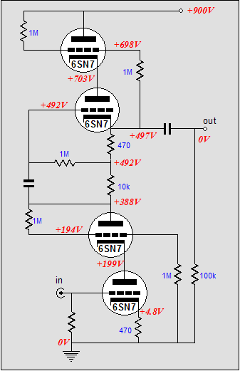
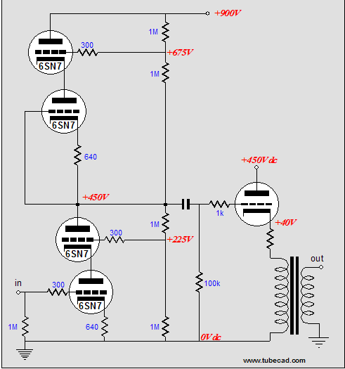
Note that this manual specifies a 450-volt limit for use in both class-A and vertical deflection amplifiers. In the Aikido circuit, the triodes enjoy a life-preserving feature in that the triodes are in series with another triode, so that both triodes must conduct for any current to flow. This arrangement greatly buffers the triode at startup, when the cathodes are cold and not conducting. In contrast, in a grounded-cathode amplifier with a plate resistor, the triode sees the full B+ voltage on its plate at startup, which can lead to cathode stripping. So how well does the Aikido topology manage as a single-ended driver stage? Using SPICE once again, with a 30V input signal, the output swing is 272Vpk and the distortion is a low 0.1%. Now 272V is almost a hundred volts better than Marty’s circuit. Not bad. Furthermore, when we include the Aikido’s excellent PSRR figure, the circuit looks even more promising. The obvious downside is worrying about the poor 6SN7s. A different type of tube, however, would lessen our worries: for example, a 6BX7 or 12B4 would make good candidates. Another downside is having to use a total of three heater power supplies per channel, as the Aikido’s top triodes, its bottom triodes, and the output tube all require a separate heater power supply. An additional downside is that we run up against the 6SN7’s maximum plate dissipation limit of 3.75W. Ideally, we run the driver stage at a respectable 10mA, but such a high current would lead to 4.3W of plate dissipation. One workaround would be to double up on the 6SN7s, by using two in parallel. Another trick is to alter the topology a tad:
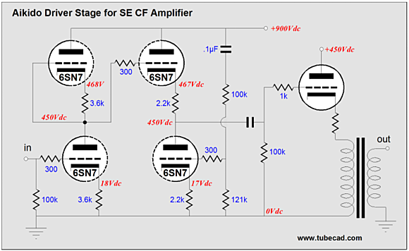
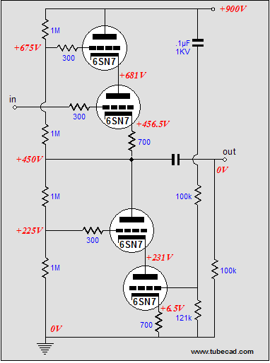
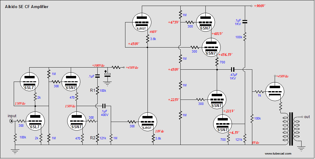
In the above schematic, we see four 6SN7 triodes in series, each displacing a fourth of the B+ voltage. As the output voltage swings positive, the topmost triode’s cathode pulls up, giving the triode below it more breathing room. Conversely, as the output voltage swings negative, the bottommost triode’s plate sees its plate voltage diminish by half the voltage swing. What is missing is an input stage to drive the driver stage. Well, did you really imagine that I would not suggest another Aikido amplifier for the job? An Aikido amplifier with a 6SL7 input tube and a 6SN7 output tube would be a good choice, as we need a gain of at least 30, which the 6SL7’s gain of 35 fits nicely. This Aikido amplifier does not require a 900V power supply, as 300-400 volts is adequate. So, what does the whole amplifier look like?
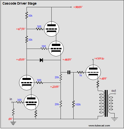
Aikido, Aikido, Aikido! Is this all you can come up? I am sure a few are thinking this, so here is a cascode driver stage that might work well as a driver stage for the cathode-follower output stage.
I came up with this circuit fifteen years ago for an OTL amplifier, as it required some big voltage swings and high gain. This is not a generic cascode, but an ultra-linear cascode amplifier, as its top triode sees 50% of the plate voltage swing. Nonetheless, the gain comes at a price. The distortion is quite high.
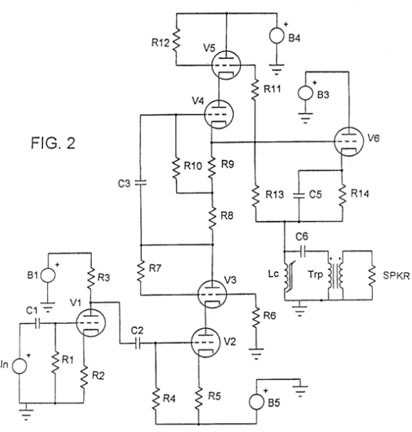
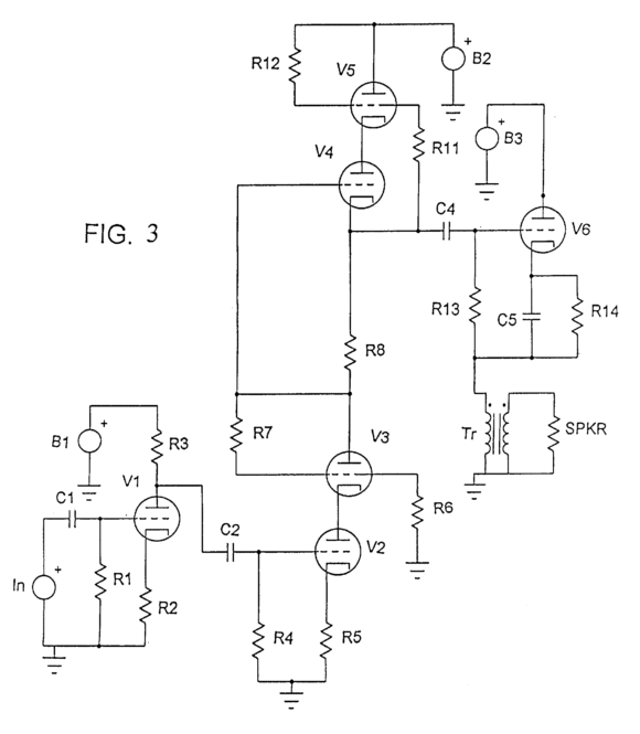
P.S. Here are two more schematics from Martin Reiffin's patent.
A bipolar power supply and DC coupling between driver stage and output tube. Yet, the cathode resistor and bypass capacitor are retained. Why? Furthermore, the negative power supply rail's noise will be greatly amplified, just as it was in Jeb's amplifier.
Nonetheless, neither of the these two variations will yield a greater voltage swing than the Marty's original circuit. //JRB
|
|
|||


| www.tubecad.com Copyright © 1999-2006 GlassWare All Rights Reserved |