| John Broskie's Guide to Tube Circuit Analysis & Design |
| |
|||||||||||||||||||||||||||||||||||||||||||||||||||||||||||||||||||
22 January 2005 Aikido e-mail Subject: Tubes: Aikido Amplifier Revisited Power supply noise reduction is only half of the Aikido’s virtues—possibly the smaller half. This circuit offers an amazing amount of flexibility, as different input and output tubes can be easily interchanged, as long as they share the socket pin-out and heater voltages. Because the circuit uses symmetrical triodes in place of plate and cathode resistors, a 6AQ8, 6BC8, 6BK7, 6BS8, 6CG7, 6GU7, 6FQ7, and 6N1P could be interchangeably used in an Aikido amplifier designed for 6DJ8s. Remember, tubes are not yardsticks, being more like car tires—they wear out. Just as a tire’s weight and diameter decrease over time, so too the tube’s conductance. So the fresh 6DJ8 is not the same as that same 6DJ8 after 2,000 hours of use. But as long as the two triodes age in the same way—which they are inclined to do, as they do the same amount of work and share the same materials and environment—the Aikido amplifier will always bias up correctly, splitting the B+ voltage between the triodes. Additionally, unless regulated power supplies are used for the B+ and heater, these voltages will vary at the whim of the power company and your house’s and neighbors’ house’s use, usually throwing the once fixed voltage relationships askew. Nevertheless, the Aikido amplifier will still function flawlessly, as it tracks these voltage changes symmetrically. Moreover, the Aikido amplifier does not make huge popping swings at start up, as the output does not start at the B+ and then swing down a hundred or so volts when the tube heats up, as it does in a ground-cathode amplifier. Most importantly, the circuit produces far less distortion than comparable circuits. The triode is not as linear as resistor, so ideally, it should not see a linear load, but a corresponding non-linear load. An analogy is found in someone needing glasses; if the eyes were perfect, then perfectly flat (perfectly linear) lenses would be needed, whereas imperfect eyes need counterbalancing lenses (non-linear) to see straight. Now, loading a triode with the same type of triode works well to flatten the transfer curve out of the amplifier. Furthermore, the Aikido amplifier—like other Aikido techniques I have tried—seems to bypass much of the power supply squirrelliness, making the circuit sound as if it were attached to batteries or a well-regulated power supply. (This includes the sonic traces left by imperfect power supply capacitors.) So, in sum, we get quite a bargain in the Aikido amplifier: low noise, low distortion, low output impedance, and no global feedback loop. Really, quite amazing.
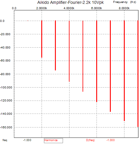
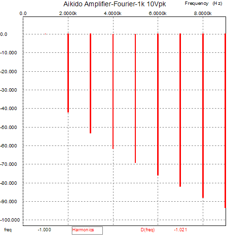
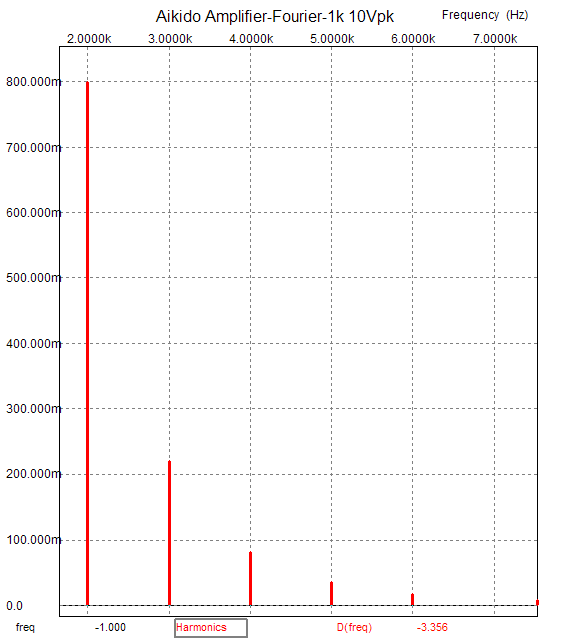
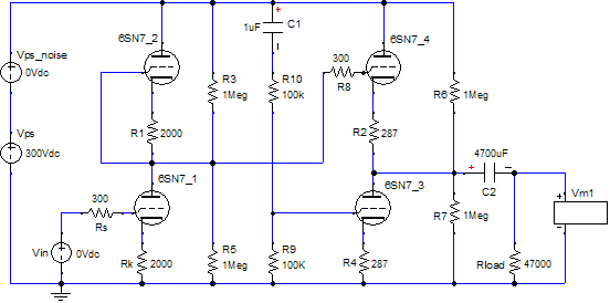
Reality check 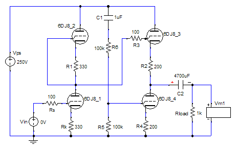 Above is a schematic of the circuit used in the B² Spice A/D simulator. The idle currents were close with 8.22mA for the first stage and 11.88mA for the second stage. The advantages a circuit in SPICE enjoys are that all the resistors and capacitors are 0.000000000001% tolerance parts and all the triodes, pentodes, transistors, MOSFETs, and JFETs match perfectly and the power supply holds zero noise and zero output impedance—quite unlike reality. As a consequence we should expect better performance in SPICE than in grubby reality. And our expectations were fulfilled, as we can see in the slightly better results from doing the same array of varying-load-resistance-at-10volts-peak tests that Bjørn had actually tested the Aikido amplifier under.
The code to deciphering dBs into percentages is percent = 100 x 10^(dB/20), where the dBs retain their negative sign. For example, 0dB = 100% . The actual Aikido amplifier I plan on building is shown below (I have to dig out my drill press out of storage).
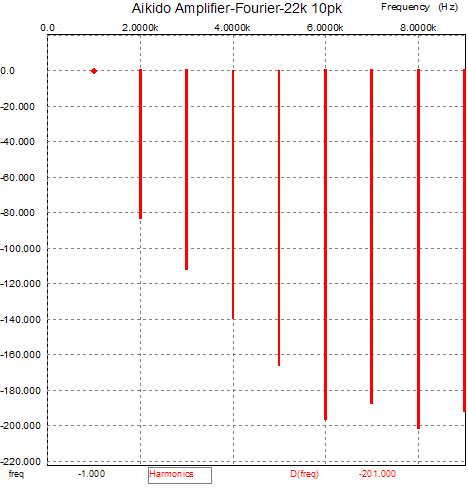
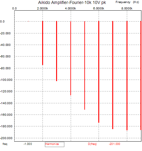
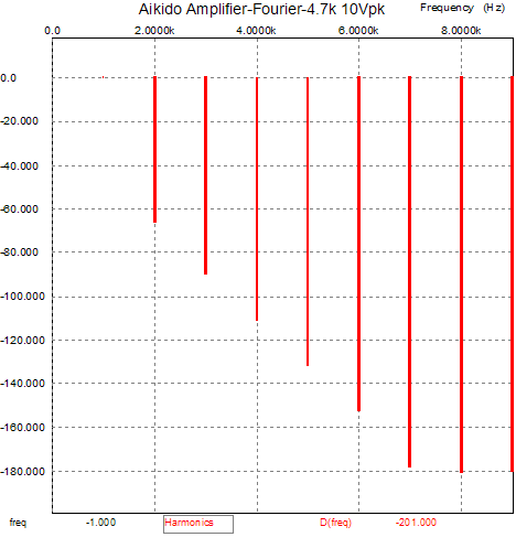
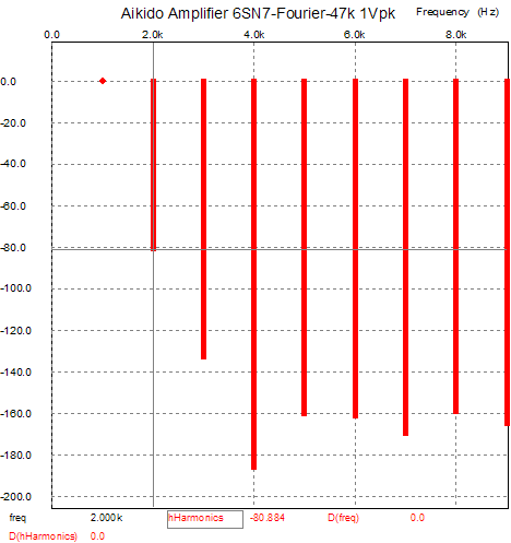
The results in SPICE look simply marvelous:
Once again, -80dB equals 0.01% distortion. Reality is unlikely to beat the simulation, but I bet it comes close to matching it. Next time—how I wish I had more time for the journal—we will look into adding a snazzy new feature to the Aikido amplifier. //JRB |
The Tube CAD Journal's first companion program, TCJ Filter Design lets you design a filter or crossover (passive, solid-state or tube) without having to check out thick textbooks from the library and without having to breakout the scientific calculator. This program's goal is to provide a quick and easy display not only of the frequency response, but also of the resistor and capacitor values for a passive and active filters and crossovers. TCJ Filter Design is easy to use, but not lightweight, holding over 60 different filter topologies and up to four filter alignments: While the program’s main concern is active filters, solid-state and tube, it also does passive filters. In fact, it can be used to calculate passive crossovers for use with speakers by entering 8 ohms as the terminating resistance. Tube crossovers are a major part of this program; both buffered and un-buffered tube based filters along with mono-polar and bipolar power supply topologies are covered. . Downloadable version (4 Megabytes file). |
||||||||||||||||||||||||||||||||||||||||||||||||||||||||||||||||||


| www.tubecad.com Copyright © 1999-2005 GlassWare All Rights Reserved |