| John Broskie's Guide to Tube Circuit Analysis & Design |
| Broskie-Macaulay Amplifier
|
||||
4 February 2005 
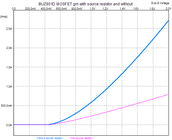
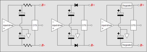
Something about Jeff Macaulay’s amplifier always troubled me—beyond the claims of single-ended class-A operation. That something lies in an asymmetry in output devices’ transfer curves; this is a mismatch that cannot be eradicated with tightly matched output devices, as the unevenness is imposed externally to the devices. In essence, the bottom output device benefits from the 1-ohm resistor at its emitter/source/cathode, as it provides local degeneration (feedback), straightening the device’s transfer curve. In contrast, the top output device is only burdened by the 1-ohm resistor at its collector/drain/plate, as it offers no useful degeneration and only steals valuable B+ voltage from the output device. Local degeneration? I have been told that at the 2004 European Triode Festival (ETF and, no, I didn't attend) they held a shoot out between cathode-bias devices: a resistor, a bypassed resistor, an LED, a battery… After a suspense–building pause, the winner was the unbypassed cathode resistor. (Although I agree with the results and I would have been truly surprised if they were otherwise, I would like to know how the test was setup, as differing gains and output impedances could easily pollute the test’s cleanliness.) Really, the only surprise was that such a result was surprising for so many. Using a tube as an example, an unbypassed cathode resistor lowers the grounded-cathode amplifier’s gain and distortion, but raises its output impedance. Why does the distortion go down? The resistor is the same current path as the plate resistor, so it will see all the variation in current flow that the plate resistor sees, which means that the input signal will be imprinted across this resistor (in phase with the input signal). Thus, if a 100k-plate resistor develops an output signal of 10 volts, then a 1k-cathode resistor will develop a signal of 0.1 volts. The signal strength at the cathode can be found from this formula: If this signal at the cathode exactly equaled the input signal in all but amplitude, then the distortion would vanish from the plate, as the tube would have to have produced zero distortion to create such equality. Real tubes do distort and that distortion is present on the unbypassed cathode resistor. This distortion is in voltage anti-phase with the input signal. For example, if the cathode voltage is too low compared to the grid’s voltage, the tube will increase its conduction, which will lift the cathode voltage. On the other hand, if the cathode voltage is too high compared to the grid’s voltage, the tube will decrease its conduction, which will drop the cathode voltage. In other words, feedback. The larger the cathode resistor’s value, the more feedback. Below is a graph of a power MOSFET with and without a source resistor (1 ohm). Note how much transconductance (gm) was lost (hold a ruler to the screen) and how much more linear the transfer curve is. The unbypassed resistor produced a good amount of feedback, but at the cost of gm.
The formula for the decrease in a MOSFET's gm because of an unbypassed source resistor is: A triode's decrease in gm because of an unbypassed cathode resistor is:
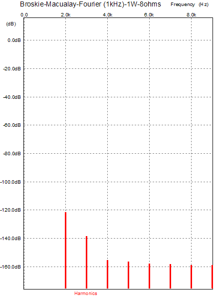
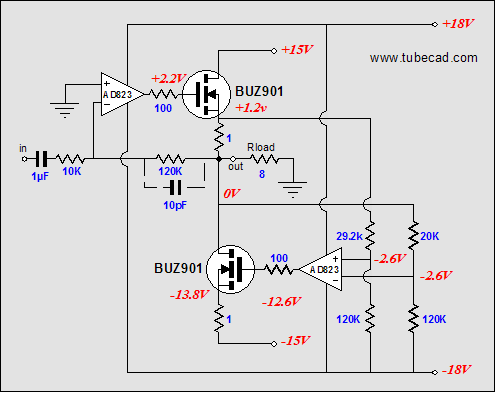
Wait a minute Returning to the Macaulay circuit, if we move the sense resistor from the top device’s collector/drain/plate to its emitter/source/cathode, what would result? Well, the output device’s transconductance would decrease along with its nonlinearity, so the OpAmp will have to swing slightly more output voltage to compensate, which in the solid-state version is not that big a liability. Additionally, the top output device is better protected from a shorted output, as the 1-ohm resistor limits the maximum current flow through the device. Most importantly, the top and bottom output devices' transfer curves would match eachother. Below is the revised circuit: 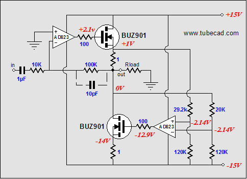 In breif, the transistors have been swapped out with MOSFETs; the idle current is now a healthy 1A; the AD823 OpAmp works particularly well in this application, as it can swing to within 0.5V of its rail voltages; the input coupling capacitor both limits the low-frequency amplification and allows full DC feedback to maintain a low DC offset at the output (yes, the amplifier inverts the phase, but the loudspeaker leads can be reversed); the amplifier can be re-wired for no phase inversion, but the capacitor cannot be eliminated, as it is needed to prevent high DC offsets at the output. All in all a good little amplifier, perfect for annoying audiophiles who like to spend lots more money. It only puts out 7 watts, but then many 300B SE amplifiers only put out 7 watts. Of course, the 300B is likely to sound more powerful than this amplifier, as its clipping can never be as sharp as this amplifier’s, as a transformer-based amplifier can never accept as much negative feedback because of the phase shifts through the transfomer. Still, if I owned a $3,000 300B amplifier I would be afraid to put it up against this amplifier, as its distortion products have a distinct single-ended quality to them, as shown below. Note the second and third are about all there is and note how low they are relative to the fundamental. If reality were only half as good as these SPICE simulation, we would still have an excellent amplifier.
Further enhancements
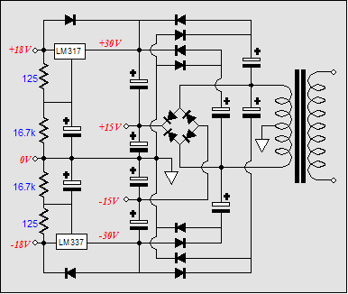
This is a problem all follower-based output stages face: the driver circuit needs to work with a greater B+ voltage than the output stage, as it must swing a greater output-voltage swing than the output stage, particularily with a MOSFET output stage. Yet, most designers are loath to add a second power transformer. Instead, they will add a series resistor and decoupling capacitor and hope that too much voltage isn’t lost; or, they may only place a rectifier in series with the existing power supply, so that when the output stage force the rail voltage to collapse, the driver stage and input stage’s power supply capacitors will not discharge into the main power supply. The better solution is to add full-wave voltage doublers to each rail, creating new rail at twice the power supply’s nominal voltage. These new rails can then be passively or actively smoothed. Below is a such a voltage-doubled power supply circuit.
7 watts? //JRB |
Only $12.95
Download or CD ROM www.glass-ware.com |
|||


| www.tubecad.com Copyright © 1999-2005 GlassWare All Rights Reserved |