(continued from 12/03/2004 )
The computer OTL amplifier started out as an experiment to see how a fairly simple and small OTL amplifier could be built if the load impedance was moved up to 32 ohms. Things started out well, as it looked as if as much as 32 watts could be had from two 6AS7 envelopes per channel. The spoiler was the high distortion that came from the low idle current and high plate voltages. The triode’s plate-dissipation limit prevented us from upping the idle current while retaining the high B+ voltage. Halving the B+ voltage allowed doubling the idle current, which linearized the output stage, greatly reducing the distortion, but at the cost of reducing the available output wattage to 4-5 watts, which although not much, should prove adequate to the task of driving a pair of computer loudspeakers. Besides, do you want a small cup of a fine restaurant’s most delicious soup or a big bowl of Campbell’s?
However, since the input and driver stages derived their power supply voltages from the output stage’s power transformer, their power supply voltage were halved as well. Low B+ voltages and 12AX7s (and most high-mu triodes) do not go together well, as the high mu means that the grid is much more effective than the plate in controlling the current flow through the tube. In other words, high-mu usually means high rp, which means high voltages will be needed.
Thus, my fear was that 320 volts would be insufficient for the 12AX7s. Well, it turns out that I had been too nervous. While more B+ voltage would have been put to good use, the 320 volts were enough to cleanly drive the output stage to full power.
I soldered together the output stage and driver stage for some tests. The results were promising. With no input stage and with 12AX7 driver tubes and 6AS7s output tubes, the distortion was better than 0.1% at one watt out into 32 ohms. My signal generator only puts out 10 volts, so I could not directly use it to test the output stage at full power out, as the driver and output stage define one large buffer amplifier with slightly less than unity gain. I used a step-up transformer to test the output stage at full power, but I didn’t want to test the distortion with a cheap transformer in the signal path. (By the way, I used two massive, 200-watt, 16-ohm load resistors in series to define a 32-ohm load, which looked ridiculous over built to the task of dissipating 4.5 watts.) The output impedance was a little over 1 ohm, which is great considering the 32-ohm load. The high-end frequency limit was easily over 100kHz, which considering the 10k grid-stopper resistors I used for the 6AS7s, isn't bad at all.
I had been wondering how well the 6N1P would work in the driver stage, so I gave it a try, after rescaling the values. The results were not as bad or good as I had expected. The output impedance doubled, but the distortion grew to more than 6 dB worse. My guess is either that the 6N1P less linear than the 12AX7 or that the 12AX7’s nonlinearity nicely complements that of the 6AS7, bring the total distortion down further than mere feedback theory would incline us to imagine.
How did it sound? I had only built up one channel and it had no input stage. Still, I wanted to find out, so I placed a Sony D-FJ401 portable CD player in the circuit and I placed an 8-ohm loudspeaker in series with the 32-ohm dummy load. The little sound that immerged was smooth, but too dim to readily evaluate. I then nervously hooked up one of my Sennheiser HD650 earpieces to the output. Not bad at all, considering the noise coming from an half-shielded amplifier.
Below is a complete schematic, which holds all the part values. The resistors are all ½W (unless otherwise marked).
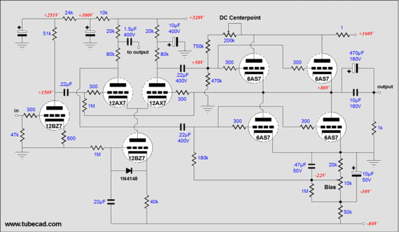 Click on image to see closeup
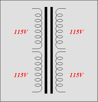
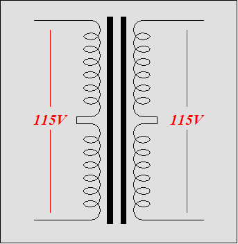
The power supply requires two transformers, one for the heaters and one for all the rest. The main power transformer makes use of a readily available configuration, as shown below.
 Click on image to see closeup
This sort of transformer is used to either isolate identical AC voltages or to step-down or step-up AC voltages. The most common use is to make 115-VAC and 230-VAC equipment interchangeable. I have seen 1000VA transformers like this sell for as little as $25 in electronic surplus stores.
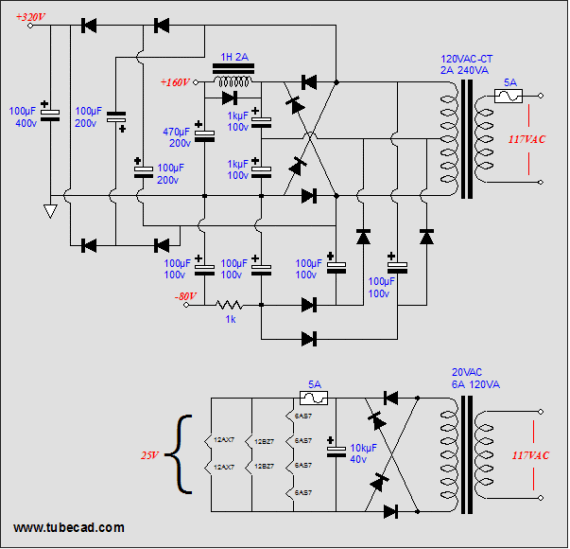
The OTL amplifier’s power supply is made up of three sub-circuits, which create the three power supply voltages needed: +320 volts for the input and driver stages, +160 volts for the output stage, and –80 volts for the driver stage’s constant-current source and the output stage’s negative bias voltage.
The output stage power supply connection must be able of delivering 1A (500mA per channel), which is trivial for solid-state amplifiers, but heavy for tube amplifiers. The choke can be just about any value of inductance, as long as the RDC is low. (One danger with chokes is the inductive kicks that result at startup and shutdown. I would look into replacing the shunting diode with a zener.)
The heater can pose a real headache, if we let them. With a 6.3-volt power supply, all the heaters would draw about 12A, as each 6AS7 draws 2.5A. This is a heavy current draw and it will require a heavy cable and rectifier bridge to deliver it. On the other hand, with a 25-volt power supply, all the heaters would draw about 3A. Much better, although the amplifier will now act like a Christmas tree in that pulling one output tube out of its socket will disable all the other output tubes. As for DC referencing, I would first try floating the heater’s power supply with a 0.1µF capacitor to ground.


