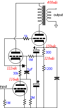
but maybe not jiggling. In the event of a driver tube failing or being removed, the voltage at the grid of the output tube falls. Beyond safety, the use of a current source yields high gain and low noise as it allows the full amplification factor of the driver tube to be utilized and it buffers the driver tube's plate from the power supply noise. This load certainly beats the puny, albeit necessarily so, plate resistor that is usually used in the Loftin-White amplifier. If the plate resistor were larger in value, the direct coupling would have to be eliminated, as the bias voltage for the output tube derives from the voltage drop across this resistor. If -30 vdc is needed and the driver tube's idle current is 1 mA, then the plate resistor must equal only 30k, which is not much of a load for a 12AX7 or 6SL7. On the other hand, the effective impedance of a current source is mu times greater than the plate resistor:
R = rp + (mu + 1)Rak,
which if we use a 12AX7 with a Rak of 30k,
R = 62000 + (100 + 1)30000
R = 3092000.
Of course, the 3 meg represented by the current source will be shunted by the 2 meg resistor that connects to ground. Still, 1.2 meg is a healthy load impedance compared to the trivial 30k load of the conventional Loftin-White circuit. The gain of a Grounded Cathode amplifier is given by the following formula:
Gain = muRa / [rp + Ra + (mu + 1)Rk]
Substituting values with the 30k load,
Gain = 100x30000 .
62000 + 30000 + (100 + 1)1100
Gain = 14.7
or with Rk bypassed,
Gain = 32.6.
Substituting values with the 1.2 meg load,
Gain = 100x1200000 .
62000 + 1200000 + (100 + 1)1100
Gain = 87.4
or with Rk bypassed,
Gain = 95.
The current source version tripled the gain and reduced the noise level as well.
SRPP Loftin-White
An alternative approach would be to use an SRPP circuit within the Loftin-White amplifier. The main advantage of this variation lies in the tight fixing of the bias voltage for the output tube. The current source loaded variation, like the conventional version of the Loftin-White amplifier, suffers from the looseness of the bias voltage setting, which could be no better than the relative match between driver tubes, against other tubes of the same type and against itself over time. In contrast, the SRPP version offers a tight bias voltage setting. Why? Because the output is taken at the cathode and not at the bottom of resistor Rak. In DC terms, the cathode is tightly locked by the voltage the grid sees. The cathode voltage can only vary by the reciprocal of the mu of the driver tube used. In other words, although variation between driver tubes will yield differing AC gains, the DC difference between cathode voltages will be very small. Tube removal and jiggling are not much of a concern with this variation on the Loftin-White amplifier, as the DC voltage will fall when the driver tube pulled from its socket.
// JRB
|
pg. 18 |
||
|
|
||