| Portable Tube A Confession I am disappointed to say that I have not done what I hoped to do: actually build and test a variety of complete tube headphone circuits by this issue. I have tested just the output stages of the single-ended and the push-pull amplifiers. The push-pull certainly looks better on the scope, but no listening tests were performed. Alas. A Recap In the last issue, we specified three design goals of a portable tube headphone amplifier:
Realistically, these design criteria required our using either a conventional AC-to-DC power supply or a DC-to-DC converter. In the first example, an AC source that would power the heaters directly and drive the primary of step-up transformer, whose secondary would then be rectified for the B+ voltage. In the second example, a low voltage DC source from either a wall wart or batteries would be for direct use on the heaters and for driving a DC-to-DC converter for establishing the plate voltage . The 72 volt DC-to-DC converters from Newport Components, i.e. the NMT1272SZ and the NMT0572SZ, were recommended. While these devices are relatively cheap, their output voltage carries a noise penalty of 1.2 volts. Fortunately, this noise is at 85 kHz and can be easily filtered out by using common-mode chokes or even simple pi filters. Two approaches to configuring these DC-to-DC converters were examined: placing the outputs of the two converters in series or in parallel with each other. The series arrangement yields a higher voltage that allows a push-pull totem pole output stage; the parallel, a higher-current power supply suitable for a single-ended OTL output stage. |
Now that we have retraced our steps, we can move forward. Let's begin by examining two possible circuits: a simple single-ended transformer coupled amplifier and a White cathode follower push-pull amplifier optimized for PSRR. Transformer Coupled Amplifier What could be simpler than a transformer coupled amplifier? Using an output transformer might be the best choice, as the transformer would provide both a better impedance matching between tube and headphone and a means of protecting the headphone from the damagingly high DC voltages. Finding a high quality low wattage output transformer is difficult, however. But one candidate is the single-ended OPA.5S-5 from Antique Sounds. Its specifications claim a .5 watt output into either a 100 or 32 ohm tap, a primary impedance of 5k and maximum idle current of 50 mA (this might be its peak current rating). The construction is open frame and it stands 2 inches tall. I do not know of a source from which to buy this transformer. But if it pans out, the design is simple enough: either one or two triodes in parallel loaded by the transformer. An idle current of 10 mA yields a 125 mA output into the 32 ohm tap or 71 mA into the 100 ohm tap. This assumes that the plate can swing far enough to sustain such a current delivery.
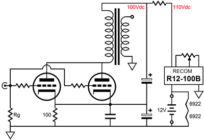
The problem of power supply noise that is created by the DC-to-DC convertor is handled post filtering the voltage leaving the DC-to-DC converter (a Recom R12-100B) with a simple RC filter and by using my trick of introducing a small amount of power supply noise at the cathode of the output tube so that the plate experiences the same amount of noise as the B+ connection, which will cause the riipple to null at the output.
|
|
| www.tubecad.com Copyright © 2001 GlassWare All Rights Reserved |