The second factor is that an over-specified transformer might sit in your amplifier. For example, a transformer might have a 6.3 winding rated at 5 amps, which means that when loaded by a 1.26 ohm load, the current into the load will equal 5 amps and the voltage across the load will equal 6.3 volts. Depending on how good the transformer's regulation figure is, a lower or higher resistance load will see a lower or higher voltage. A regulation figure of 10 percent means that when free of any load, the transformer's output voltage will be 10 percent higher than stated (6.93 VAC in this case). Now 10 percent is actually a fairly good amount of regulation, as many transformers have 30-40 percent regulation figures. (Usually, the bigger the transformer, the lower the regulation figure.) Returning to our example, if an amplifier that sported two EL34s and two 6SN7s also came with the transformer with the 5 amp rating for its 6.3 volt tap, then the 1.5 amp draw from the EL34 and the 0.6 amp draw from the 6SN7 will only add up to a 4.2 amp draw, which would under-load the transformer's 6.3 volt tap, thus increasing the voltage from this tap.
Why wasn't the transformer specified for 4.2 amps? Probably because the transformer manufacture did not offer one off the shelf at that value and the amplifier company did not want to incur the added cost of using a custom designed transformer. (This is less true for old equipment and close to always true with modern designs, as off the shelf transformers are the choice of low production amplifier makers. "If Magnequest doesn't make it, we won't use it.")
Rather than induce needless fear, the quick test is to measure the voltage across the heater pins of the tube's socket when the amplifier is in use.
[Of course, you will be careful not to electrocute yourself in the process, as I do not want to receive any angry e-mail from some reader's bereaved spouse. Remember that the heater winding is often floated at some voltage higher than ground potential.]
If the voltage measured exceeds the 6.3 or 12.6 nominal voltage, then several remedies present themselves. The easiest solution is to add a resistor in parallel with the heater string to drag down the voltage. This is effective, but ill advised, as it only further burdens an already taxed amplifier if the amplifier is now seeing more voltage at the wall socket than it was designed to see. A better solution is to place one low-valued resistor in series with each leg of the heater string. These resistors will absorb the excess voltage and provide the added benefit of extending the life of the tubes used.
When hot, a heater's resistance can be easily calculated: resistance equals heater voltage divided by heater current draw, R = Vh / Ih. When cold, however, the heater's resistance will be much lower, as its resistance is positively temperature related. For example, an EL34 hot is equal to 4.2 ohms, but cold, only 1 ohm. Thus we have the huge surge of current at turn-on that can make a transformer shudder and a heater open circuit and fail. By adding resistance in series with the heater, the surge is lessened by the voltage drop across the resistors, which at turn-on will be much greater than during normal use. (I have been told that tests have been conducted that showed that light bulbs, a very similar technology, last at least twice as long when outfitted with current inrush limiters.) How are the values of these resistors calculated? It is easy enough:
R = Vactual - Vdesired
2 x Ih .
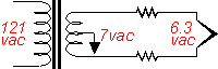
For example, if we use the EL34 based amplifier, the total heater circuit current draw was 4.2 amps. If the transformer heater winding is putting out 7.14 VAC under use, then a pair of 0.1 ohm resistors are needed:
0.1 = 7.14 - 6.3
2 x 4.2 .
|
pg. 2 |
||
|
|
||