The idle current of the push-pull output stage sets the peak (Class A) output current, 2Ip. Since we want to avoid positive grid voltages, the idle current must be set carefully. A quick calculation yields the following formula:
Ipeak = B+ / 2(rp + Rl).
This formula not only gives us the peak output current, but by extension, the value of twice the idle current, 2Ip.
One topological variation worth a second look is the Class A-AB amplifier, which is modeled after the Nelson Pass single-ended amplifier that breaks into Class AB, push-pull functioning after set output is exceed. Yes, it is something like having your cake and eating it as well. Do not forget the most import watt is the first watt. While amplifier may put out peaks of hundreds of watts, most of the listening will be in that first watt. This why crossover distortion irks the ear so much and this is why small wattage single-ended tube amps can triumph over big wattage solid-state amplifiers.
The explanation of the Class A-AB amplifier has been covered in past issues. So let's get down to the details of converting the last schematic to Class A-AB. We want the top triode to be the main single-ended tube. It will be the only output tube experiencing the current variations as it powers the headphone driver. The bottom tube will be the current source that is immune to the input signals. Up to a certain point that is. After -4.7 mA has been exceeded, we want the bottom triode to cease acting as a current source and begin acting as an active output device; and once +4.7 mA has been exceeded, we want the top triode to continue conducting current beyond twice the idle current. So what we have is one tube, the bottom one, always conducting some current and the other one only ceasing to conduct after the bottom tube begins to conduct beyond its idle current.
In other words, what we have is a modified Class AB amplifier. If the bottom tube is made to respond to the input in the same way that the top tube must, we would just have a very richly biased Class AB amplifier.
By making the bottom selectively insensitive, we have taken care of two problems with the Class AB amplifier. Class AB amplifiers were devised to correct the gross crossover distortion of the Class B amplifier. By increase the overlap between output devices, the crossover notch where neither device conducted is filled. But this overlap created a new problem: the effective transconductance of the two devices is twice that of a single device. This Gm doubling causes the output impedance to dip over the portion of the overlap. It is as if a crack in the road was repaired by placing a speed bump over it. Where the notch caused one disturbance in the waveform, the Gm doubling causes two, one where the bottom tube ceases to conduct and one where the top tube ceases to conduct. Second, these disturbances often occur in the first few watts where the ear is very sensitive.
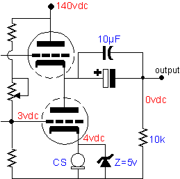
The Class A-AB overcomes these two problems by eliminating Gm doubling mechanism and by shifting the transition point between tubes to outside the first few watts. Below is the output stage from the last schematic altered to function as a Class A-AB output stage.

The idle for the output stage is set by the current source. Since 4.7 mA is the limit for the small current regulating diodes, we will choose this value as the idle value. The top triode will function as the amplifier sole output device within ± 4.7 mA, which means that it will
|
|
||
|
pg. 21 |
||