|
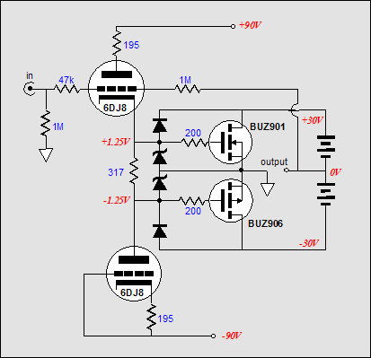
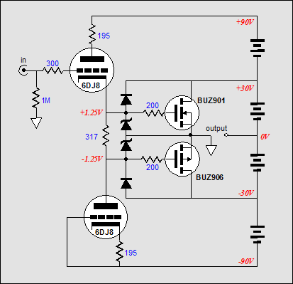
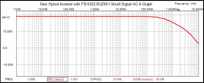
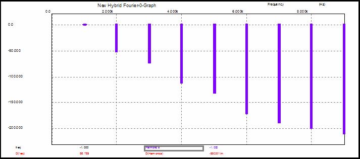
Since the output is inverted relative to the triode’s grid, a feedback resistor can bridge grid to output. Now the ratio between the input resistor and the feedback sets the amplifier’s gain. The problem is that feedback resistor is of so high a value that any stray capacitance will bring the high frequency response down. Lower-valued resistors could be used, but then the input resistor would load down the line stage’s output. The sneaky technique would be to apply the feedback to the top triode’s plate and the bottom triode’s cathode. The next amplifier schematic makes this clear. Here the power supplies act as direct shorts for the output signal. For example, imagine that a +1V pulse were forced on the amplifier’s output. The top triode would see a greater cathode-to-plate voltage and would conduct more current, which would pull its cathode up by 1/mu. Conversely, the bottom triode would see a lesser cathode-to-plate voltage and would conduct less current, which would pull its plate up by 1/mu. Now, the top MOSFET would increase its conduction while the bottom MOSFET would decrease its conduction. Because the top MOSFET is conducting more, its drain would pull down its connection to its power supply and the output would swing down: feedback, in other words. The triodes act as feedback resistors and they set the gain of the amplifier. So, is the gain of this amplifier 33, the mu of the 6DJ8? No, it is closer to 10 because the resistors in the input stage are not bypassed. Should these resistors be bypassed? No, as it increases the amount of distortion beyond the increase in gain. In fact, the triodes nicely complement the MOSFETs and the distortion is reduced beyond what we would expect from feedback alone. Below is a B² Spice A/D schematic and simulation of this topology. The circuit differs slightly from the one above it, as I was exploring different ways to reduce distortion. Thus, the added resistors in series with the power supplies to simulate the power supply’s DCR and 0.45 resistor at the top MOSFET source. This resistor reduces the N-channel MOSFET’s transconductance so that it might better match the P-channel MOSFET’s naturally lower transconductance. (I’ll admit it: it is so much easier to tweak an amplifier in SPICE than it is on an actual workbench. Of course, once you are happy with the results in SPICE, go the workbench to confirm.) First of all, note the wide bandwidth: flat from DC to 100k. Second, note the beautifully decreasing harmonics. (One advantage to this feedback arrangement is that few people would recognize it as such, which means that it could be touted as being “feedback free” in high-end-audio magazines if one were so inclined..) |
|
www.tubecad.com Copyright © 2003 GlassWare All Rights Reserved |
|
More ð |
