|
|
series with the cathode. This idea is not original, but taken from "other" circuitry.
Briefly: as a teenager in the early 60's I built tube amps. 12AX7s, 6L6s and the like were some of my "best" childhood friends. In the late 60's I went on to BJT amps. In the 80's moved to FET amps and a couple years ago became a self proclaimed follower of Nelson Pass and his minimalist ways. So I AM NOT KNOCKING TUBES! I greatly enjoy your analysis of circuits and marvel at your ability to come up with new ones, or at least ones I have not seen before. Keep up the great work!!
Jim (Colorado)
Jim, thanks for the suggestions. The reality check headphone amplifier was not meant to be a definitive solid-state headphone amplifier, rather it was presented as a good-sounding cheap alternative to an expensive and complex tube circuit. If the tube circuit failed to beat the Op-Amp, why bother?
Were I to design a definitive solid-state headphone amplifier, it would be based on discrete, hand picked transistors or MOSFETs. Or possibly, it would consist of only a LH0033 zero feedback buffer with a DC servo, battery power supply, and a healthy idle current.
I expected at least one e-mail concerning the resistor connected to the output of the Op-Amp in the reality check headphone amplifier. This resistor serves two purposes: the first is to provide a bias current for the IC voltage reference and the second is to shunt out half of the Op-Amp's output transistors and force the Op-Amp output stage to work as single-ended Class-A amplifier. Most Op-Amps run a miniscule idle current through their output transistors, so only a small amount of unilateral current drag will shut off half of the output stage. The remaining "on" transistor now must counter the tug towards the negative rail by pulling the output to ground level. Thus, by placing the resistor between output and voltage reference, both goals were achieved.
Thanks for the tips on the MOSFETs. The headphone amplifier used a transistor because it makes for a greater output voltage swing, as the transistor only needs to see a .7 volt base-to-emitter difference to conduct; the MOSFET, 3 to 4 volts.
The RIAA EQ curve can be realized by many topologies. However, using a choke in place of a cathode resistor will set in place a 6 dB per octave
|
|
|
|
low pass filter. Unfortunately, the output impedance at the plate will climb with increasing frequency and with this climb the PSRR will drop, adding more noise to the output.
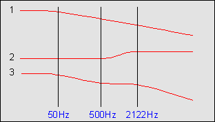
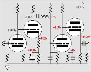
One trick might be to only bypass the cathode resistor with a small valued capacitor. This capacitor will result in a skewed frequency response: flat up to the transition frequency, then a 6 dB climb to some breaking frequency, and flat thereafter. In other words, a high frequency booster, much like a tone control would impose. Wait a minute, doesn't that run counter to the required RIAA EQ curvature? Yes, it does. But if we impose a low pass filter centered on the 50 Hz point of the curve first, then the boost will then cancel the a portion of the decline and the final curve will achieve the desired RIAA EQ. The following circuit gives a rough idea of how to implement it.
Editor
Energy Free California
|
|

