|
|
0.0047 S; and, would the plate resistance, rp, fall from 33K down to 1.7K? In short, as the screen and plate voltages converged, the tubes would gradually assume the triode operational characteristics?
Earles
Tucson, AZ, USA.
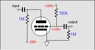
Both the grid and screen control the current conduction in a tetrode or pentode. The grid exercises more control than the screen, so it can be said to have greater amplification factor. In other words, ±1 volts of signal at the grid might require ±10 volts of signal at the screen to equal the same change in current flow. The plate also exercises a control over the tube's conduction. The plate, however, is only 1/mu times as effective as the grid. In fact, the screen can be used as the output terminal and the plate can be used as the controlling element, albeit with a greatly reduced gain and dissipation limit. Even with the triode, the grid can be attached to the load resistor and the plate becomes the effective "grid."
This information is not meant to be practical, only informative. The thing to remember is that both the triode and the pentode are really modified diodes. The cathode emits electrons, which the plate receives when it is more positive than the cathode. If the plate is made negative to cathode, it stop receiving electrons, but it does not cease to have an effect on the flow of electrons from cathode to a positive charged grid. In this case, we still have a triode like function, but with reordered roles.
|
|
|
|
that can barely conduct at all. Connecting the screen to the plate, makes for a low mu triode with a low rp. Connecting the grid to the cathode and using the screen as the control element, makes for a low mu triode with a high rp. It is the connections that matter most. Having the plate and the screen share the same DC voltage does not make a triode out of the pentode. AC connecting the screen to the plate does make a triode.
The connection may only be partial, as it is an ultra-linear amplifier. Here the screen receives only a portion of the AC signal at the plate. The greater the percentage of plate signal, the closer the tube comes being a triode. Conversely, the less the percentage, the closer to being a pentode.
Subject: Medium Gain Line Stage Amplifier
(sep 1998)
First I would like to thank you for your excellent web-magazine. Because of your comprehensible written articles, I am able to learn with every article.
I would like to build your design for a medium gain line stage amplifier (September 1998). But there is a small problem. The design with the 12BH7 seems perfect with just the right amount of amplification, but it is not that easy to find those tubes in the Netherlands.
I would like to you use the ECC82 instead of the 12BH7, the ratings of the ECC82 look rather similar to the 12BH7. But having learned a lot form your articles, I am still not able to calculate the right values.
Could you help me with the right values or perhaps with the right formulas so I can calculate these values myself? (I also need to know the right wattage for the resistors.)
Luuk
The Netherlands
The ECC82, AKA 12AU7, is definitely usable, although I prefer to use a more robust tube. if we retain the same B+ voltage of 300 volts, the plate and cathode load resistors should be increased to 20k and the bias resistor should be 562.
While there is a formula that gives us the cathode resistor value, it is based on the assumption that the triode is perfectly linear. It isn't. The best plan is to review the plate curves and find where the grid intersects with desired plate voltage and idle current.
|
|
|
|
I have long desired to build a line stage or power amplifier that used a grid-amplifier, as this topology has been called. My motive is not better sound, but the potential for baffling a few tube gurus I know.
The greater the voltage on grid, the screen, or the plate, the greater the conduction. Connecting the screen to the grid, makes for a super high mu triode
|
|
|
