|
|
Subject: Transcendent OTL
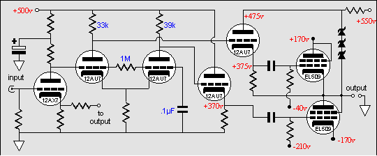
I want to refer to schematic of the Transcendent OTL in you November 1999 issue http://www.tubecad.com/november99. It appears to me that the totem pole is operating at different gain despite of the claim.
The upper tube is a cathode follower, so it is bootstrapped to compensate for the 100% feedback so it's of unity gain. But the lower tube is still a common cathode stage with some gain of EL509. The driver stage has no feedback to reduce the gain of lower tube to the same level as the upper tube. It appears that a lot more negative feedback is required to correct this, do you agree?
Another thing is that the drive requirement for full output is as follow, assuming 90% efficiency of the cathode follower.
Upper tube:
Drive voltage = (grid voltage swing / 0.9) + output voltage.
Bottom tube:
Drive voltage = grid voltage swing
And thus the total drive required must be the same as upper tube, am I correct?
p. k.
?
Yes, your insight is right on. The patented equalization drive signal mechanism implemented in the Transcendent OTL, the basis for starting the company in fact, does not equalize the drive signal for the bottom and top tubes. Sad to say, I cannot recommend this trick for anything other than ensuring that the top cathode follower has some plate voltage available to it, which adding a hundred volts to the driver stage power supply would also ensure.
|
|
|
|
In other words, the zeners diodes helps this amplifier out of the corner the designer had painted it into to: at idle, the bottom cathode follower sees 130 volts from cathode-to-plate and the top cathode follower only sees 100 volts. (Using a 5687 instead of the 12AU7 would be a better choice for the cathode followers, as the 5687 has a greater low voltage operating range.) But it does not equalize the drive signals for the output tubes. To verify this disconnect the feedback resistor and observe the output waveform (my choice is the triangle-wave, as its straight lines reveal bending much more readily than the sine-wave). An added sad fact is that long tail phase splitter's plate resistors were chosen to ensure an equal output voltage swings from the plate resistors, which is not what the output stage needs to deliver a clean output voltage swing.
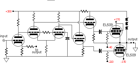
So how do we fix this amplifier? The easiest path would be to couple the long tail phase splitter's second plate resistor to the top of the zener string, rather than to the B+ connection. On the next page you will find the schematic. This modification will equalize the drive voltage for the bottom output tubes (and is covered in this issue's article on hybrid amplifiers). Now the tubes are both working as cathode followers. A positive pulse applied to the output will be bucked equally by both tubes, as the pulse will be relayed to the bottom tube's grid and the top tube's grid is fixed. Once again, to verify this proposition disconnect the feedback resistor and observe the output waveform. Your formulae will not apply here, but would (minus the / .9) if the zener string is attached to the long tail phase splitter's first triode's plate resistor instead. Maybe in the next issue, we will do a complete rework of this and other OTL amplifiers, cleaning up power supply noise problems and equalizing drive voltages.
|
|