|
|
|
|
|
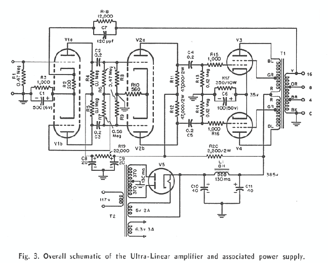
The complete amplifier circuit is relatively simple, inexpensive, and efficient. With a 370-volt power transformer at 130-ma peak requirement, power output is almost as high as for a tetrode amplifier and twice that of a triode amplifier with cathode bias and the same power
supply. No adjustments are necessary for balance either of the phase inverter or of the output-stage plate current, and there are no critical values of capacitors or resistors required. The amplifier is driven to 20 watts of output with an input of only 0.7 volt. Feedback is carried around the complete circuit in an external loop. There are 20 db of feedback in this loop as measured under load conditions (about 30 db based on open circuit gain), and a
|
|
|
|
|
|
|
|
|
|
safe margin is maintained. A small capacitor across the feedback resistor increases the feedback in the region above 100 kHz to smooth the high-frequency response. This capacitor is not required to keep the amplifier stable though it does add to the stability margin. Performance of the Amplifier.
All stages of the amplifier have been adjusted for minimum intermodulation, and the IM curves based on sine-wave power output are shown in Fig. 4. These curves were run using frequencies of 40 and 2,000; 40 and 7,000; 40 and 12,000; 100 and 2,000; and 60 and 7,000, all mixed four to one. The IM is almost identical under all conditions of test indicating that it is completely independent of frequency,
|
|
|
|
|