| John Broskie's Guide to Tube Circuit Analysis & Design |
14 April 2024 Post Number 600
Post 600 My reply was, "Hell, I don't expect myself to have read every post I have made." Ditto, my having written them. My guess is that it will take at least another decade to hit number 1,000. If I wrote shorter posts, I could do it in a few years; but as so many old-timers, a group to which I now begrudgingly belong, die upon arriving at some milestone, such as reaching 100 years in age, it might be a better goal for to aim for the further away decade. In search of possible inspiration for this post, I reread William H. Gass's essay, "Retrospection," written to commemorate his turning 87. (Gass died six years later in 2017, age 93.) Although an enjoyable and yet intensely depressing read, for me at least, no inspiration poured forth. Here is a small example from his essay:
I would have made a proper noun out of "Future," for in that sentence it is a noun doing a verb (fears), not an adjective describing a plural noun—but still that's some dang fancy writing. However, since Gass had a 32 year head start on me, my future doesn't look as obviously truncated as did his, with my slice of cake still covering much of the plate. (Gass's lifelong aim was to indict humanity, which prompted many dark paragraphs, wherein he exquisitely described and catalogued the inexcusable. In contrast, Nabokov's lifelong aim was to discover beautiful, but still unidentified, butterflies.)
New Product: 12Vac Balanced CF
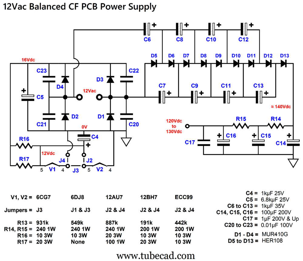
The rectifier circuit on the left creates 16Vdc from the 12Vac voltage. Resistors R16 and R17 are in parallel and drop 4V of DC voltage, making 12Vdc available to the tube heater elements, which can be wired either in series or in parallel, depending on the tubes' heater voltages. The rectifier circuit on the right develops a whopping 140Vdc, which the following RC filters both smooth and reduce to 130Vdc at the triode plates. One big advantage to running a lower B+ voltage is that we can use large-capacitance capacitors; for example, C14 & C15 & C6 hold 100µF each, which is what an old tube-based power amplifier might have used for its output stage.
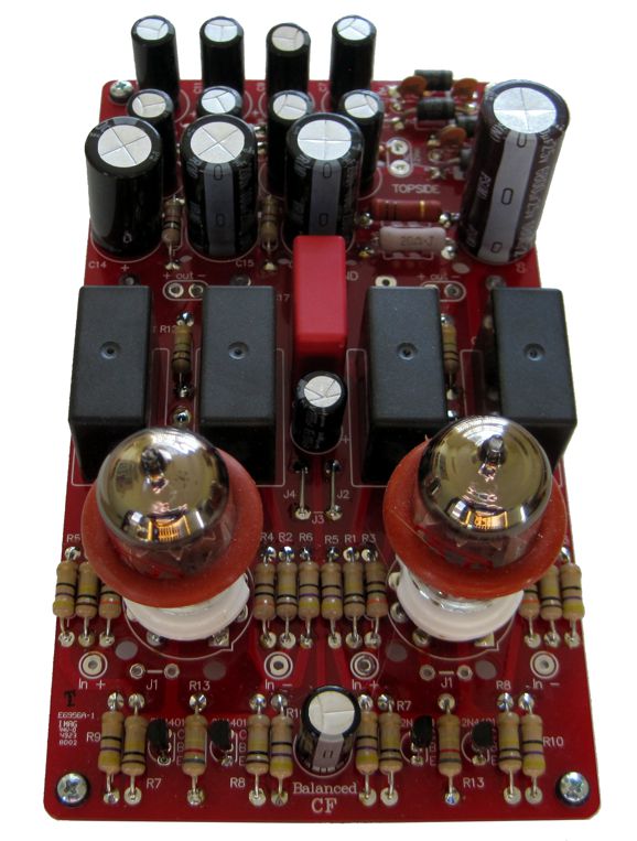
With 6DJ8 or 12AU7 tubes, a 12Vac 24VA wallwart power transformer can be used; with the other tube types, a 30VA wallwart should be used due to the higher heater current draw. Of course, an internal power transformer could be used. The 12Vac Balanced CF PCB holds two balanced cathode follower circuits with fancy constant-current source loading, which both provides distortion-reduction and enhanced PSRR (via some Aikido mojo). In other words, the PCB is for balanced stereo use, holding two channels, four outputs. The key word here is "balanced." The design doesn't just hold four regular cathode followers that could be used independently. Instead, each channel's balanced cathode followers require a balanced input signal, as the distortion-reducing constant-current sources strive to deliver a balanced output. By the way, the idea behind this design appeared in post 585 from last year. The form the circuit took was that of a balanced buffer for driving high-impedance headphones. I was so tickled by the design that I had to add some Aikido mojo and create a PCB for it.
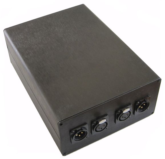
Note the low-voltage NPN transistors (2N4401) used. Resistors R7 and R8 bridge the two outputs, so should see no signal at their junction. If the output balance is off, a small error signal appears which the constant-current sources work to rebalance. Jumper J1 grounds the internal shield found in some twin-triode tubes, such as the 6AQ8 and 6DJ8. Also note cathode resistors R5 and R6, which are optional. Without them, the output impedance is lower; with them in place, the cathodes are shielded from external shunting capacitance. (In the 1950s it was discovered that naked cathode followers got into trouble when trying to directly drive high-capacitance loads. Mind you, this is not likely in a stereo system where low-voltage, low-bandwidth signals prevail.) Resistor R13 and capacitor C3 inject Aikido mojo, resulting in an improved PSRR. Resistor R13's value depends on the tube type used. The power-supply schematic shown above lists the values for four different tube types. The way the Aikido mojo works is a small amount of B+ voltage ripple is fed to the bases of the balanced NPN transistors, which creates a small antiphase current conduction, just great enough to force a power-supply-noise null at the output. Since each tube type offers a different transconductance, each tube type presents a different output impedance, which in turn requires a different amount of antiphase current conduction, hence the differing R13 values. I installed the assembled 12Vac Balanced CF PCB in an extruded aluminum enclosure.
The clamshell box is 3in tall, 6in wide, and 8.5in deep. We don't get to see the glowing tubes, but then the tubes do not get blasted by the bass sound waves. The black anodized aluminum enclosure acts as a heatsink of sorts, as circulating air currents in the box move the heat to the inner box surface and then to the outside air. At the front, we see the AC power jack. (I have yet to add a power switch.)
The PCB is 4in by 7in:
The PCB and parts will soon be available at the GlassWare store.
More Thoughts on Recoil-Free Drivers
I pointed out that we could get clever and use the existing magnet structure for both the front and rear voicecoils:
Well, my new thoughts are that two voicecoils could appear on the same side, but move in anti-phase to each other, which would still result in no recoil action.
Note that the voicecoil attaching to the cone will suck up the air behind the cone's dust-cap and loudspeaker spider, when it pushes forward, rarifying the air; but compressing the trapped air when it moves backwards. If an air pathway is provide between the two voicecoils, the antiphase movements would cancel. How do we create an air pathway? We could use super-strong rare-earth neodymium magnets found in hard-drives.
The softly-rounded magnet corners would help prevent turbulence. My second thought is that we could use the secondary voicecoil to attach to the cone.
This returns us to having loudspeaker drivers that suffer from recoil, but this problem could be sidestepped in a loudspeaker by using two woofers, one firing forward, one firing backwards (something not easily done with headphones); or one firing left, the other, right. The huge outer voicecoil would get a good grip on the cone, thereby lowering distortion. Indeed, if the cone material was pliant enough or if a secondary surround encircled the inner voicecoil and dust-cap, we could drive the two voicecoils with different signals from a crossover, with the center voicecoil and dust-cap acting as the high-frequency driver. Imagine making a coaxial driver along these lines. So many ideas, so little time.
Cathode-Follower Input Stage for Inverting Solid-State Amplifier
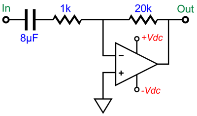
Note the 1k input resistor and the 8µF input coupling capacitor. The math behind the capacitor is simple: Capacitor = 159155/R/Freq Where the result is in µF and Freq is the low-frequency cutoff. Let's say you fancy ultra-expensive platinum-foil coupling capacitors. Since a 0.1µF fancy coupling capacitor can cost $80, an 8µF capacitor might cost $800 or $8,000 or… Well, there is a way to DC couple a cathode follower to the 1k input resistor. We begin by exploiting the differential input stage of the solid-state power amplifier.
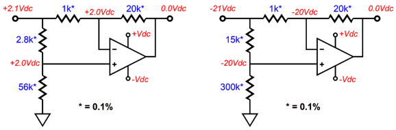
Note that both the non-inverting and inverting inputs see the exact same two-resistor voltage divider resistors. Thus, no matter what the input voltage is, the output remains locked at zero volts. The resistor tolerance must be supremely tight for this trick to work, which means that 1% is far too loose. The next step is to realize that as long as the two voltage dividers yield the same voltage division, different valued resistors can be used. For example, the following setups work equally well.
The ratios remain the same, as 20k/1k = 56k/2.8k = 300/15k = 20 to 1. You might be thinking: great you have developed a power amplifier that cannot amplify. You want amplification? No problem.
AC input signals are amplified, but not DC voltages. Effectively, the capacitor sees a resistance equal to 1k||20k or 952 ohms. Thus, if we want the low-frequency bandwidth to extend down to 20Hz, the capacitor value should equal 159155/952/20 or 8.35µF, with 10µF being close enough. Okay, what if we do not shunt the capacitor with a 20k resistor, using a much larger-valued resistor instead? As long as the voltage divider ratio is the same, we should be good to go—except that if the chip amplifier holds a transistor-based input stage, we can expect a bigger DC offset at its output. On the other hand, if the solid-state amplifier holds a FET-based input stage, such as are used by the Burr-Brown (now TI) chip amplifiers, such as the OPA549, we can get away with using higher-valued resistors.
This arrangement also extends down to 20Hz, but uses only a 0.51µF capacitor. Hell, we could use 51k and 1.02M resistors—if we can find a 0.01% 1.02M resistor—which would require a 0.16µF capacitor. Next, we add tubes.
The 5mA constant-current source is needed to deliver more current into the 6DJ8. The 1k resistor and 100µF RC filter extend low-frequency bandwidth to below 1Hz. The DC offset at the amplifier's output should prove low, as both of its inputs see roughly the same resistance. One remaining problem we encounter is the relatively poor PSRR of the cathode follower. Because triodes exhibit rp (plate resistance), increasing the cathode-to-plate voltage prompts an increase in current conduction; a decrease, a reduction in current flow. In other words, the rp will provide a path for the B+ voltage ripple to leak out the cathode. On the other hand, if we replace the triode with a pentode or a depletion-mode MOSFET, their high plate resistance or drain resistance prevents most of the ripple from leaking through. My workaround, of course, is to add some Aikido mojo.
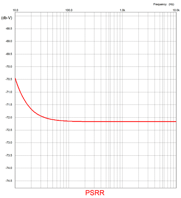
This arrangement purposely leaks a small fraction of the B+ voltage ripple into the non-inverting input, thereby forcing a power-supply noise null at the output. In SPICE simulations, the improved PSRR was staggering. Without the Aikido mojo additions, the PSRR at the 6DJ8's cathode is -32dB. This might seem impressive, but only due to our forgetting about the power amplifier's gain of +26dB, which reduces the PSRR to just -6dB. With the Aikido mojo additions, the PSRR at the amplifier's output is -72dB! Mercy.
Of course, this does not mean we should fail to reduce the high-voltage B+ voltage noise, as simple RC filtering would go a long way to improving the PSRR. If the solid-state power amplifier holds a FET-based input stage, then the following setup could be used.
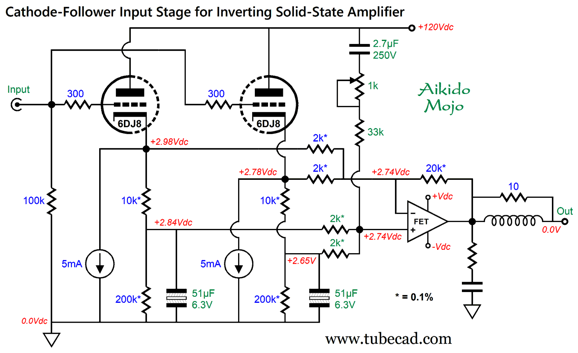
The 10k and 20k resistors greatly unload the 6DJ8's cathode, which lowers the signal loss through the cathode follower. The potentiometer was added due to the optimal resistor value falling between 33k and 34k. In general, I dislike potentiometers, especially when DC current flows through the wiper and the resistance film, but in this setup no DC current flows.
Here we see both the 6DJ8's triodes being used, which allow us to use larger valued negative feedback resistors. Note the discrepancy in idle current between triodes; yet no DC offset occurs, as the two sets of 2k resistors average the voltages. Each triode sees a 1666-ohm load to AC signals. By the way, the two constant-current sources can be terminated to the negative power-supply rail that the solid-state chip amplifier uses.
Note the addition of two safety diodes, which prevent the cathodes from being pulled down to the negative power-supply rail voltage at startup. In addition, they prevent the non-polarized capacitors from seeing an over voltage and the solid-state chip amplifier from latching up from too great a negative input stage voltage. In other words, the diodes prevent the cathodes from ever exceeding -0.7 volts, while the constant-current sources get extra voltage headroom.
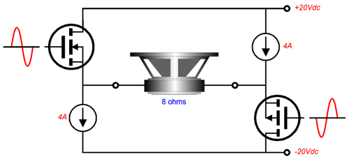
SE Vs PP Single-Ended Versus Push-Pull He didn't disagree with the 25% maximum theoretical efficiency, but with the Fourier graph, arguing that the N-channel MOSFETs' inherent non-linearity would have to impart a single-ended harmonic signature. He went on to claim that since an N-channel MOSFET's current conduction could easily exceed that of its constant-current-source loading, the resulting output waveform would look very single-ended indeed. Is this true? No. First of all, the N-channel MOSFETs can never exceed constant-current source current limit, as constant-current sources are misnamed, since they are actually regulators and limiters of current —much in the same way that voltage regulators are voltage limiters. For example, if the constant-current sources are set to 2A of current flow, the maximum flow through the loudspeaker voicecoil is 2A. To see why this is so just imagine that one of the MOSFETs was replaced with a jumper wire, a wire that might be able to pass 2,000A of current before melting. The loudspeaker would still only see a maximum of 2A of current flow, as the only path to the negative power-supply rail voltage is through the 2A constant-current source.
Yes, the N-channel MOSFET's transfer function is not linear, but that is not enough to make a single-ended signature, as the two output MOSFETs work in opposition, so the two nonlinearities must be superimposed upon each other, just as they would in any other push-pull output stage that uses the same polarity output devices, such as the Circlotron and the transformer-coupled. The result is a cancellation of even-order harmonics. On the other hand, if we use N-channel and P-channel MOSFETs with the two constant-current sources, we will get single-ended harmonic signature.
With this arrangement, the MOSFETs can break through the constant-current source limit, which is revealed by simply replacing both MOSFETs with jumper wires.
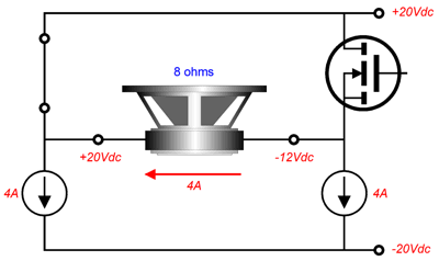
The loudspeaker voicecoil see a voltage differential of 40V, which divided by 8 ohms equals 5A, one ampere more than the constant-current source allow. If we completely cease any current conduction through the two MOSFETs, we get the following result.
The two output MOSFETs are effectively open-circuits. The constant-current sources enforce their 4A current limit, and the loudspeaker only sees a 32V voltage differential. Here is the transfer-characteristics graph for the IRFP250 N-channel MOSFET.
Sadly, few MOSFET datasheet show this type of graph. Note the nonlinear turn-on slope up to 10A of current conduction. Well, this is the region that the MOSFET will operate within the single-ended-bridge configuration shown above. The P-channel MOSFET transfer looks much the same, but going negatively. Put all together, we get a single-ended output waveform.
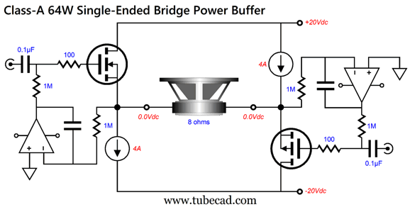
In other words, this bridge output stage will peak more positively than it will negatively. It is a single-ended output stage, as the output devices conduct in current phase, which is the best definition of "single-ended" operation, just as anti-phase current conduction of output devices is the best definition of push-pull operation. Here is a fleshed-out schematic.
This class-A buffer will dissipate 320W at idle, which puts the efficiency at 20%, 5% less than the theoretical efficiency. A strong, balanced, tube-based line-stage amplifier with a gain of 20dB could drive this power buffer to full output. (I would add some high-frequency filtering to the inputs.) If we halved the bipolar power supply voltages and the constant-current source current flow, we would quarter the idle dissipation and audio power output. Nonetheless, 16W of single-ended power can prove glorious.
Music Recommendation: Saturday Night in San Francisco
I discovered that both Amazon Music and Qobuz offer an extended version of the album in 24-bit, 192kHz resolution.
Now, we are talking—and listening. Indeed, I listened to half of the tracks with my new Sennheiser HD 660S headphones, and I am eager to hear the remaining tracks on loudspeakers. These three master guitarists (at their peak) play together so seamlessly that it is as if a single guitarist with six arms and six hands were playing three guitars at once. Breathtaking—without any exaggeration. Highly recommended. //JRB
Did you enjoy my post? Do you want to see me make it to post 1,000? If so, think about supporting me at Patreon.
User Guides for GlassWare Software
For those of you who still have old computers running Windows XP (32-bit) or any other Windows 32-bit OS, I have setup the download availability of my old old standards: Tube CAD, SE Amp CAD, and Audio Gadgets. The downloads are at the GlassWare-Yahoo store and the price is only $9.95 for each program. http://glass-ware.stores.yahoo.net/adsoffromgla.html So many have asked that I had to do it. WARNING: THESE THREE PROGRAMS WILL NOT RUN UNDER VISTA 64-Bit or WINDOWS 7, 8, and 10 if the OS is not 32-bit or if it is a 64-bit OS. I do plan on remaking all of these programs into 64-bit versions, but it will be a huge ordeal, as programming requires vast chunks of noise-free time, something very rare with children running about. Ideally, I would love to come out with versions that run on iPads and Android-OS tablets.
|
I know that some readers wish to avoid Patreon, so here is a PayPal button instead. Thanks.
John Broskie
John Gives
Special Thanks to the Special 99 To all my patrons, all 99 of them, thank you all again. I want to especially thank
I am truly stunned and appreciative of their support. In addition I want to thank the following patrons:
All of your support makes a big difference. I would love to arrive at the point where creating my posts was my top priority of the day, not something that I have to steal time from other obligations to do. The more support I get, the higher up these posts move up in deserving attention.
If you have been reading my posts, you know that my lifetime goal is reaching post number one thousand. I have 400 more to go. My second goal was to gather 1,000 patrons. Well, that no longer seems possible to me, so I will shoot for a mighty 100 instead. Thus, I have just 16 patrons to go. Help me get there. Thanks.
Only $12.95 TCJ My-Stock DB
Version 2 Improvements *User definable Download for www.glass-ware.com
|
|||


%20Cover.png)


| www.tubecad.com Copyright © 1999-2024 GlassWare All Rights Reserved |